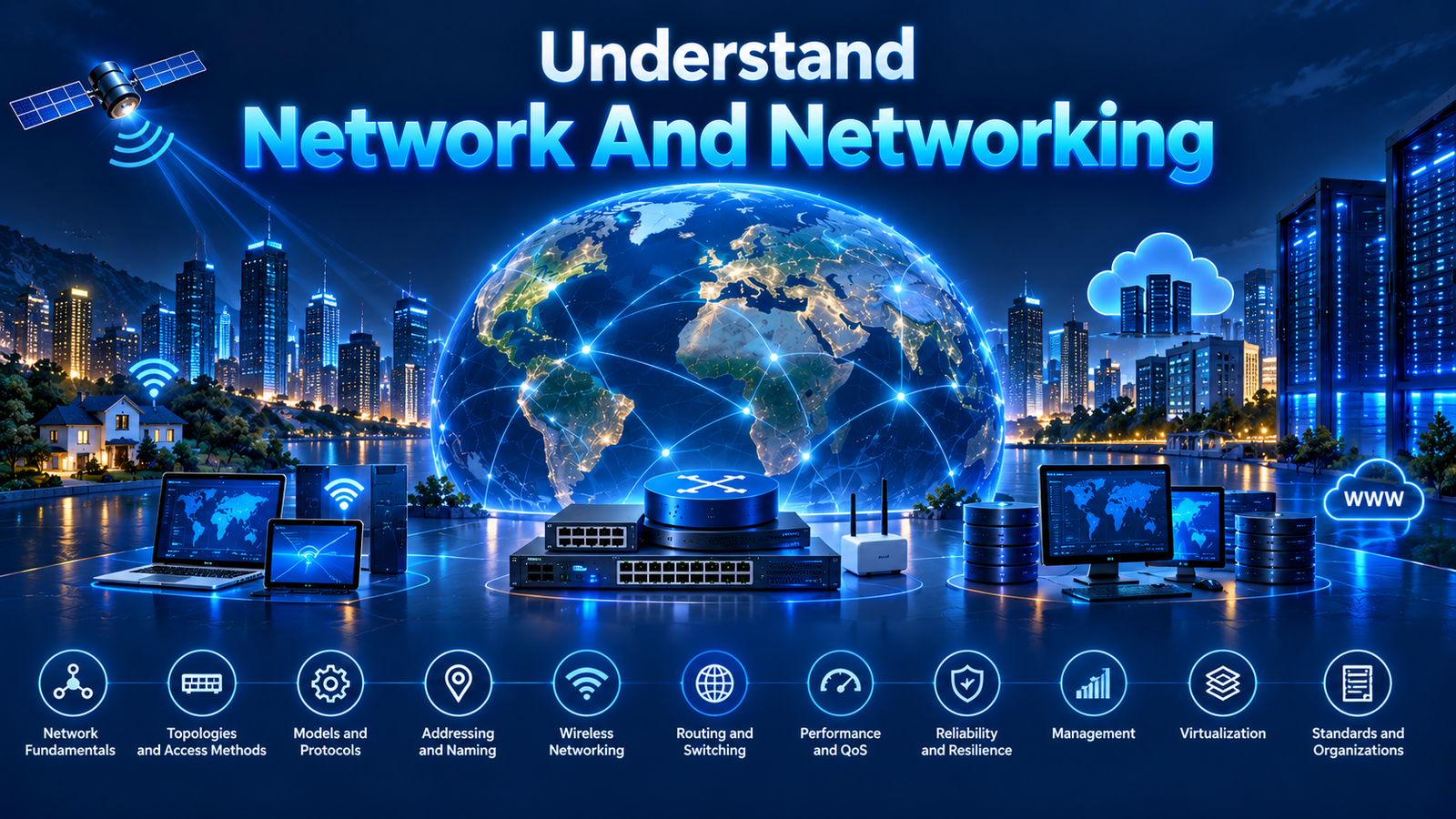
Understand Network and Networking
Introduction
The earliest computer networks were primarily designed to connect computers so they could communicate and share information. As computing evolved, networking expanded far beyond connecting desktop computers and servers. The rapid growth of digital technologies has transformed networking into the communication fabric that interconnects virtually every type of computing system.
Today, networks connect a diverse range of computing nodes, including desktop computers, laptops, servers, smartphones, tablets, wearable devices, Internet of Things (IoT) devices, industrial controllers, robots, autonomous and connected vehicles, medical devices, smart home systems, smart buildings, transportation systems, utility infrastructure, manufacturing equipment, cloud platforms, edge computing systems, artificial intelligence (AI) platforms, and billions of embedded devices operating across homes, enterprises, industries, cities, and critical infrastructure.
These interconnected computing nodes continuously exchange data to support communication, automation, monitoring, control, analytics, collaboration, and intelligent decision-making. Every digital interaction—including web browsing, email, cloud computing, multimedia streaming, online collaboration, digital payments, industrial automation, telemedicine, smart transportation, and connected public services—depends on reliable network connectivity.
Networking therefore extends far beyond connecting devices through cables or wireless signals. It is an engineering discipline that encompasses the architecture, technologies, communication protocols, standards, security, management, and operational principles required to enable reliable, efficient, scalable, interoperable, and secure communication between interconnected computing nodes.
Network
What is a Network
A Network is a collection of nodes interconnected through links that form a connected structure.
Networks exist in many forms and domains, but they all share the same fundamental principle of interconnected nodes linked together to achieve a specific purpose.
A network provides a framework through which nodes are connected, enabling relationships, movement, interaction, exchange, or communication depending on the purpose of the network.
Elements of a Network
Every network, regardless of its purpose, implementation, or domain, is fundamentally composed of two essential elements: nodes and links. Together, these elements define the structure of a network and determine how nodes are interconnected.
Nodes
A Node is an identifiable point within a network that participates in the operation of the network. Depending on the type of network, a node may generate, receive, process, store, forward, distribute, or otherwise participate in the flow of information, resources, materials, energy, or services.
The role of a node varies depending on the type of network. For example, in a transportation network, nodes represent airports, railway stations, or road intersections. In an electrical power network, nodes represent power plants, substations, and transformers. In a social network, nodes represent individuals or organizations. In a computer network, nodes represent computing devices such as computers, servers, routers, switches, smartphones, sensors, and other interconnected systems.
Links
A Link is a physical, logical, or conceptual connection between two or more nodes within a network. It establishes the relationship or path through which nodes are interconnected.
The nature of a link varies depending on the type of network. In a transportation network, links represent roads, railways, air routes, or shipping lanes. In an electrical power network, links represent transmission and distribution lines. In a social network, links represent relationships between individuals or organizations. In a computer network, links represent the physical or logical communication paths that enable data to be exchanged between interconnected computing nodes.
Nodes and links together form the fundamental building blocks of every network. Regardless of the complexity, size, or purpose of a network, every network can be represented as a collection of interconnected nodes joined through links.
Computer Network
What is a Computer Network
A Computer Network is a collection of interconnected computing nodes connected through network links that enable the exchange of digital information.
Computing nodes are devices capable of generating, processing, storing, forwarding, or receiving data. These nodes exchange digital information through physical or logical network links using standardized communication protocols.
Computer networks interconnect a wide variety of computing nodes, including desktop computers, laptops, servers, smartphones, tablets, routers, switches, firewalls, Internet of Things (IoT) devices, industrial controllers, sensors, cloud computing resources, virtual machines, containers, edge computing platforms, artificial intelligence (AI) systems, and numerous other connected devices.
By interconnecting these computing nodes, computer networks enable data exchange, resource sharing, access to applications and services, distributed computing, remote access, and digital communication across local, metropolitan, and global environments. They form the communication backbone of the digital world, supporting web browsing, email, cloud computing, multimedia streaming, industrial automation, digital payments, artificial intelligence, and critical infrastructure.
Elements of a Computer Network
A computer network is composed of multiple interconnected elements that work together to enable data communication between computing systems. Each element performs a specific function, and collectively they provide the infrastructure required for connecting devices, transmitting data, controlling communication, delivering services, and supporting network operations.
Although computer networks vary in size, architecture, technologies, and applications, they all consist of a common set of fundamental elements. These elements define how a network is constructed, how information flows between interconnected computing nodes, and how communication is established, managed, and maintained.
The fundamental elements of a computer network include:
Computing Nodes
Computing nodes are the devices or systems that participate in a computer network. They serve as the source, destination, or intermediary for digital communication by generating, processing, storing, transmitting, receiving, or forwarding data. Computing nodes include end-user devices, servers, network infrastructure devices, Internet of Things (IoT) devices, cloud resources, virtual machines, and other interconnected computing systems.
Network Links
Network links establish the physical or logical connections between computing nodes. They provide the communication paths through which digital information travels across the network. Depending on the network architecture and communication technology, network links may consist of wired or wireless connections that support data transmission between interconnected devices.
Communication Media
Communication media provide the transmission medium through which digital signals travel between interconnected computing nodes. They carry electrical, optical, or radio-frequency signals that transport data across the network. Communication media are broadly classified as guided (wired) media, such as twisted-pair cables, coaxial cables, and optical fiber, or unguided (wireless) media, such as radio waves, microwaves, infrared, and satellite communication.
Network Devices
Network devices provide the infrastructure required to interconnect computing nodes and control the flow of network traffic. They perform functions such as forwarding data, routing packets, connecting network segments, enforcing security policies, balancing traffic loads, and enabling communication between different networks. Common network devices include switches, routers, wireless access points, firewalls, gateways, load balancers, and network interface cards (NICs).
Network Protocols
Network protocols define the standardized rules, message formats, procedures, and conventions that govern how computing nodes exchange digital information across a computer network. They ensure that devices from different manufacturers can communicate reliably and interoperably while supporting functions such as addressing, routing, error detection, flow control, session management, and data delivery.
Network Addressing
Network addressing provides the identification mechanisms required to uniquely identify computing nodes, applications, and services within a computer network. Addressing enables data to be delivered to the correct destination and supports communication across local and global networks. Common addressing mechanisms include MAC addresses, IP addresses, port numbers, hostnames, and domain names.
Network Topology
Network topology describes the physical or logical arrangement of computing nodes and network links within a computer network. It defines how devices are interconnected and how communication paths are established between them. Network topology influences network performance, scalability, reliability, fault tolerance, and ease of management.
Network Services
Network services provide the functionality required to support communication, resource sharing, network administration, security, and application delivery. They enable computing nodes to discover, connect, authenticate, exchange information, and access shared resources across the network. Common network services include DNS, DHCP, directory services, web services, email services, file sharing, remote access, network time synchronization, and authentication services.
Together, these fundamental elements form the foundation of every computer network. Understanding the role of each element provides the basis for learning how computer networks are designed, implemented, operated, managed, and secured. The following sections examine each element in detail, beginning with Computing Nodes.
Characteristics of a Computer Network
A computer network possesses several characteristics that define its capabilities and distinguish it from other types of networks. These characteristics determine how effectively the network connects computing nodes, exchanges data, shares resources, supports applications, and delivers reliable communication services.
Connectivity
Connectivity enables computing nodes to establish physical or logical connections with one another, forming the foundation for data exchange across the network.
Data Communication
Data communication enables interconnected computing nodes to exchange digital information using standardized communication protocols that ensure reliable and efficient transmission.
Resource Sharing
Resource sharing allows multiple users and systems to access and share hardware, software, storage, applications, internet connectivity, and network services.
Scalability
Scalability enables a computer network to accommodate additional users, devices, applications, and services while maintaining acceptable performance and reliability.
Reliability
Reliability is the ability of a computer network to provide consistent and uninterrupted communication through resilient network design, redundancy, and fault tolerance.
Interoperability
Interoperability enables devices, operating systems, applications, and network technologies from different manufacturers to communicate seamlessly using standardized networking protocols.
Performance
Performance describes how efficiently a computer network transfers data and delivers services. It is commonly evaluated using metrics such as bandwidth, throughput, latency, jitter, packet loss, and network utilization.
Security
Security protects network resources, communications, and connected systems by preserving confidentiality, integrity, and availability through security controls such as authentication, authorization, encryption, access control, and network monitoring.
Manageability
Manageability is the ability to configure, monitor, administer, maintain, troubleshoot, and optimize network infrastructure throughout its operational lifecycle.
Availability
Availability ensures that network resources, applications, and services remain operational and accessible whenever they are required.
Quality of Service (QoS)
Quality of Service (QoS) enables a network to prioritize different categories of network traffic based on application requirements, ensuring predictable performance for latency-sensitive and mission-critical services.
Relationship Between Network and Computer Network
A Computer Network is a specialized type of Network. While the concept of a network is generic and applicable across many domains, a computer network applies the same fundamental principles to interconnected computing systems.
Both networks and computer networks are built upon the same foundational structure consisting of nodes and links. The primary difference lies in the nature and purpose of these elements. In a computer network, the nodes are computing devices and the links are communication paths that enable the exchange of digital information.
The relationship between the two concepts can be summarized as follows:
| Network | Computer Network |
|---|---|
| A generic concept applicable across multiple domains. | A specialized implementation of a network for interconnected computing systems. |
| Nodes may represent any participating entities. | Nodes represent computing devices such as computers, servers, routers, smartphones, sensors, and IoT devices. |
| Links represent the connections or relationships between nodes. | Links represent physical or logical communication paths used for data transmission. |
| The purpose depends on the type of network. | The primary purpose is to enable digital communication, resource sharing, and service delivery. |
A computer network therefore inherits the fundamental principles of a network while introducing specialized technologies, communication protocols, network devices, addressing mechanisms, and architectures that enable reliable and secure communication between interconnected computing nodes.
Understanding the relationship between Network and Computer Network provides the conceptual foundation for studying the individual elements, technologies, architectures, and communication protocols that make modern computer networking possible.
Graph Theory
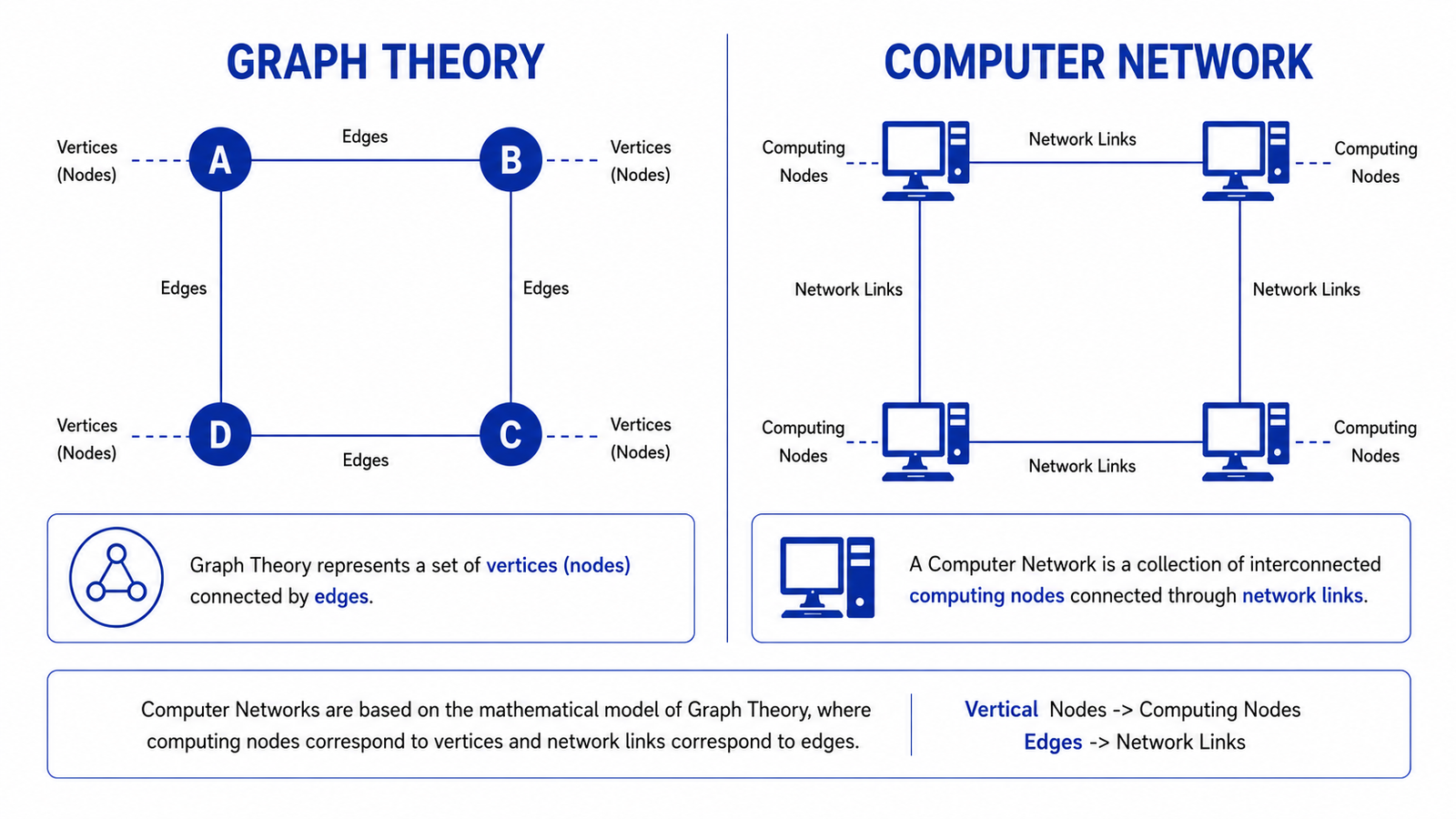
Graph theory is a branch of discrete mathematics that studies graphs, which are mathematical structures used to represent relationships between interconnected objects. A graph consists of vertices (also called nodes) and edges (also called links) that connect those vertices. Graph theory provides a mathematical framework for modeling, analyzing, and optimizing networks of all kinds, including computer networks, transportation systems, social networks, biological networks, and communication systems.
In computer networking, graph theory provides a simplified representation of a network by modeling network devices as vertices and the communication links between them as edges. This mathematical representation makes it easier to analyze network connectivity, determine communication paths, optimize routing, improve reliability, and design efficient network architectures.
Relationship Between Graph Theory and Computer Networks
Computer networks naturally fit the principles of graph theory because every network consists of interconnected devices and the links that connect them. In graph theory, each network device is represented as a vertex, while each wired or wireless connection is represented as an edge. This abstraction allows complex networks to be represented as mathematical graphs without considering the physical appearance of the network.
Graph theory enables network engineers to visualize network structures, identify communication paths, analyze connectivity, evaluate redundancy, and develop efficient routing algorithms. As a result, many networking technologies and protocols rely on graph theory to support network design and operation.
Vertices (Nodes)
A vertex is an individual point or entity within a graph. In computer networks, vertices represent the devices that participate in communication, such as computers, servers, routers, switches, printers, smartphones, and other connected devices. Each vertex represents a point where data can originate, terminate, or be forwarded to another device.
The number and arrangement of vertices determine the size and overall structure of a network.
Edges (Links)
An edge represents the connection between two vertices. In a computer network, edges correspond to the communication links that connect network devices. These links may be physical, such as twisted-pair cables, fiber-optic cables, and coaxial cables, or wireless, such as Wi-Fi, microwave, or cellular connections.
Edges determine how devices are interconnected and define the communication paths available within the network.
Graph Representation of Computer Networks
Graph theory provides a simple mathematical representation of a computer network by modeling devices as vertices and communication links as edges. This representation allows even large and complex networks to be visualized and analyzed more effectively than physical network diagrams alone.
A graph can represent either the physical connectivity of a network, showing the actual communication links between devices, or the logical connectivity, showing how data flows regardless of the underlying physical infrastructure.
Types of Graphs Used in Computer Networks
Different graph types are used to model different networking scenarios depending on how devices communicate and how data flows through the network.
Undirected Graphs
An undirected graph represents connections where communication is possible in both directions. Many Ethernet-based local area networks can be represented using undirected graphs because connected devices can generally transmit and receive data over the same communication link.
Directed Graphs
A directed graph represents communication paths that have a specific direction. These graphs are commonly used to model routing paths, packet forwarding, traffic flows, and one-way communication links.
Weighted Graphs
A weighted graph assigns numerical values, known as weights, to each edge. In computer networks, these weights may represent bandwidth, latency, transmission cost, distance, or link reliability. Routing algorithms use weighted graphs to determine the most efficient communication path between network devices.
Connected Graphs
A connected graph is one in which every vertex can reach every other vertex through one or more edges. Most operational computer networks are designed as connected graphs to ensure that all devices can communicate directly or indirectly with one another.
Applications of Graph Theory in Computer Networks
Graph theory plays a significant role in the design, analysis, and management of computer networks. It is widely used to model network topologies, analyze connectivity between devices, determine optimal communication paths, develop routing algorithms, identify redundant links, improve network resilience, optimize resource utilization, and support scalable network design.
By representing computer networks as interconnected vertices and edges, graph theory provides the mathematical foundation for understanding network structures and solving complex networking problems. Many concepts discussed throughout computer networking, including routing, topology, path selection, and network optimization, are based on the principles of graph theory.
Network Access Methods
What are Network Access Methods?
Network access methods define the rules and procedures used by devices to access a shared communication medium. When multiple devices use the same communication channel, an access method determines when a device can transmit data and how access is coordinated among devices.
Network access methods are particularly important in shared-medium networks, where simultaneous transmissions can interfere with one another. Different networking technologies use different access mechanisms based on the characteristics of their communication medium.
Media Access Control
Media Access Control (MAC) is the mechanism used to control how devices access a communication medium. It operates at the Data Link Layer of the OSI model.
MAC determines how devices access the medium, how transmission opportunities are coordinated, and how transmission conflicts are handled. The specific MAC mechanism depends on the networking technology and the characteristics of the communication medium.
Contention-Based Access
Contention-based access allows multiple devices to compete for access to a shared communication medium. A device attempts to transmit when it determines that the medium is available.
Because multiple devices may attempt to transmit at approximately the same time, contention-based methods provide mechanisms to reduce, detect, or recover from transmission conflicts.
CSMA
Carrier Sense Multiple Access (CSMA) requires a device to listen to the communication medium before transmitting.
If the medium is available, the device can attempt transmission. If another device is already transmitting, the device waits before attempting to transmit.
CSMA reduces the probability of simultaneous transmissions, although it cannot completely eliminate them because two devices may determine that the medium is available at nearly the same time.
CSMA/CD
Carrier Sense Multiple Access with Collision Detection (CSMA/CD) extends CSMA by providing a mechanism for detecting collisions during transmission.
A transmitting device monitors the medium while transmitting. If it detects a collision, the transmission is stopped and the device waits for a defined period before attempting retransmission.
CSMA/CD was historically associated with shared, half-duplex Ethernet networks. With the widespread adoption of switched, full-duplex Ethernet, collisions are no longer a normal characteristic of communication over individual switched Ethernet links, making CSMA/CD largely historical in Ethernet operation.
CSMA/CA
Carrier Sense Multiple Access with Collision Avoidance (CSMA/CA) is primarily used in wireless networks.
Wireless devices generally cannot detect collisions in the same manner as traditional shared Ethernet. CSMA/CA therefore attempts to reduce the probability of collisions before transmission occurs.
A device listens to the wireless channel and, when the channel is available, follows defined waiting and contention procedures before transmitting. Wireless networks can also use acknowledgements and optional mechanisms such as Request to Send (RTS) and Clear to Send (CTS) to help coordinate communication.
Controlled Access
Controlled access methods coordinate access to a shared communication medium rather than allowing devices to compete freely.
Transmission opportunities are controlled through an organized mechanism that determines which device is permitted to transmit.
Common controlled-access approaches include polling and token passing.
In polling, a controlling device determines which device is allowed to transmit. In token passing, a special control frame or token is passed between devices, and the device holding the token is permitted to transmit.
Controlled access can provide more predictable use of a shared medium and can reduce contention between devices.
Channelization
Channelization divides a communication resource into separate portions so that multiple devices can use the available medium in an organized manner.
The available communication resource may be divided according to frequency, time, code, or wavelength.
Common channelization techniques include:
- Frequency Division Multiple Access (FDMA)
- Time Division Multiple Access (TDMA)
- Code Division Multiple Access (CDMA)
- Wavelength Division Multiple Access (WDMA)
Channelization is particularly important in telecommunications and wireless communication systems, where multiple users need to share limited communication resources.
Role of Network Access Methods
Network access methods provide the rules required for devices to share communication resources in an organized manner. They help coordinate transmission, reduce interference and collisions, and improve the utilization of available communication capacity.
The appropriate access method depends on the characteristics of the network, communication medium, and networking technology. Shared wired networks, wireless networks, and telecommunications systems may therefore use different approaches to control access.
Evolution of Computer Networks
The evolution of computer networks represents a continuous development of technologies for connecting computers, communication systems, and distributed resources. From early packet-switched networks to globally interconnected digital infrastructure, networking evolved through several overlapping developments rather than a single linear sequence.
ARPANET
In 1969, ARPANET became operational, connecting research institutions through a packet-switched network. It demonstrated that geographically separated computers could communicate through a distributed networking architecture and became an important foundation for the development of the Internet.
Packet-Switched Networking
During the 1960s and 1970s, packet switching developed as a practical approach to computer communication. Data was divided into packets that could share network resources, improving communication efficiency and allowing networks to support multiple users and destinations.
Ethernet Networking
During the 1970s, Ethernet was developed for connecting computers within Local Area Networks (LANs). It provided a practical approach to LAN communication and eventually became a dominant technology for connecting computers and other devices within local networks.
TCP/IP Protocol Suite
During the 1970s, the Transmission Control Protocol (TCP) and Internet Protocol (IP) were developed to enable communication between independent networks. Together, they established a common framework for internetworking and provided the foundation for interconnected networks.
Analog and Dial-Up Networking
During the 1970s through the 1990s, computer systems commonly used modems to communicate over traditional telephone networks. A modem converted digital computer data into analog signals for transmission over telephone circuits and converted received analog signals back into digital data. Dial-up networking provided an important method for connecting computers to remote systems and, later, to Internet Service Providers.
Local Area Networks
During the 1970s and 1980s, Local Area Networks expanded within universities, research organizations, businesses, and other institutions. LANs enabled computers and shared resources such as printers, storage, and applications to communicate within buildings and campuses.
TCP/IP Adoption
In 1983, ARPANET adopted TCP/IP as its standard protocol suite. This was a major milestone in networking because it provided a common protocol foundation for communication between different networks and accelerated the development of the Internet.
Internetworking and Routing
During the 1980s, internetworking technologies and IP routing developed to connect separate networks. Routers provided the capability to forward packets between different networks, allowing multiple LANs and WANs to operate as interconnected networks.
Wide Area Networks
Beginning in the 1980s, Wide Area Networks expanded networking beyond local environments by connecting geographically separated networks across cities, countries, and continents. WANs evolved through multiple generations of communication and switching technologies, including circuit-switched and packet-switched services, Frame Relay, Asynchronous Transfer Mode (ATM), and later Multiprotocol Label Switching (MPLS).
Internet Expansion
During the 1980s and 1990s, TCP/IP-based networking expanded beyond research environments and increasingly interconnected independent networks. This growth established the Internet as a global network of networks and created a foundation for widespread network-based services.
World Wide Web
During the 1990s, the World Wide Web introduced a simple way to access information and services over the Internet through web browsers and web servers. Technologies such as HTTP and HTML contributed significantly to the widespread adoption of Internet networking.
Wireless Networking
During the 1990s, wireless networking developed as an alternative to physical network cabling. Wireless LAN technologies, particularly those based on IEEE 802.11, enabled computers and other devices to connect to networks using radio communication.
Mobile and Cellular Networking
During the 1990s, cellular networks increasingly moved from primarily voice-oriented communication toward digital data services. The subsequent development of 2G, 3G, 4G/LTE, and 5G progressively increased mobile data capabilities and integrated cellular networks with the Internet.
Broadband Networking
From the late 1990s onward, broadband technologies such as DSL, cable, fiber, and satellite provided higher-speed Internet access than traditional narrowband connections. Broadband networking expanded the practical use of multimedia, web applications, and other Internet services.
High-Speed Ethernet
During the 2000s, Ethernet evolved from traditional shared-media networks toward high-speed switched networks. Gigabit Ethernet and subsequent higher-speed Ethernet technologies increased LAN capacity and supported increasingly demanding applications and data-center environments.
MPLS Networking
During the 1990s and 2000s, Multiprotocol Label Switching (MPLS) developed as a technology for efficient packet forwarding and scalable WAN services. MPLS used labels to make forwarding decisions and supported capabilities such as traffic engineering and service differentiation.
Virtual Private Networks
During the 1990s and 2000s, Virtual Private Network (VPN) technologies developed to provide logical private connectivity across shared or public networks. VPNs became important for connecting geographically distributed networks and providing remote access.
Cloud Networking
During the 2000s, cloud computing introduced networking architectures in which computing, storage, applications, and other resources could be delivered as distributed services over networks. Networking became an essential foundation for connecting users, applications, data centers, and cloud resources.
Network Virtualization
During the 2000s, network virtualization enabled multiple logical networks and network functions to operate over shared physical infrastructure. This increased flexibility in data centers and became an important foundation for cloud-based networking.
Software-Defined Networking
During the 2010s, Software-Defined Networking (SDN) introduced greater separation between network control and packet forwarding. This enabled networks to be managed through software, programmable interfaces, centralized control, automation, and dynamic policy-based operations.
Internet of Things
During the 2010s, networking expanded beyond computers, servers, and conventional user devices to include sensors, vehicles, industrial equipment, appliances, and other physical objects. This development created large-scale networks of connected devices.
Data-Center and Cloud-Native Networking
During the 2010s, large-scale data centers increasingly adopted virtualized, automated, and software-defined networking architectures. These developments supported distributed applications, microservices, containerized workloads, and large cloud environments.
4G and Mobile Broadband
During the 2010s, 4G and LTE networks significantly increased mobile data capacity and reduced latency. Mobile networks became an important platform for Internet access, video streaming, cloud applications, mobile services, and connected devices.
Edge Networking
During the 2020s, edge networking and edge computing brought processing, storage, and network services closer to the systems generating and consuming data. This approach helps reduce latency, bandwidth consumption, and dependence on centralized processing locations.
5G Networking
During the 2020s, 5G networking introduced increased capacity, lower latency, greater device density, and new capabilities for mobile broadband, IoT, industrial networking, and distributed applications.
Network Automation and Programmability
During the 2020s, network automation increasingly incorporated APIs, orchestration, telemetry, software-based configuration, and policy-driven management. These capabilities reduced dependence on manual network administration and enabled networks to respond more dynamically to operational requirements.
AI-Driven Networking
During the 2020s, artificial intelligence and machine learning began being applied to network monitoring, anomaly detection, traffic analysis, performance optimization, capacity planning, troubleshooting, and automated network operations.
Intelligent and Autonomous Networking
During the 2020s, networking increasingly incorporated intent-based management, automation, telemetry, and AI-assisted decision-making. These capabilities support networks that can analyze conditions, optimize operations, detect problems, and respond to changes with reduced manual intervention.
Future of Computer Networks
Beyond the 2020s, computer networks are expected to continue evolving toward higher speeds, greater programmability, increased automation, distributed intelligence, autonomous operation, and deeper integration of cloud, edge, wireless, IoT, and AI-based systems.
Collision and Broadcast Domains
Collision Domain
A collision domain is a network segment in which multiple devices share a communication medium, where simultaneous transmissions can interfere with one another and cause a collision.
Broadcast Domain
A broadcast domain is a logical portion of a network in which devices can receive broadcast traffic. A device uses a broadcast address to send a broadcast frame, allowing the traffic to reach all devices within the same broadcast domain.
Role of Switches in Collision and Broadcast Domains
A switch is primarily a Layer 2 device in the OSI layers that connects devices within a network. Each switch port provides a separate communication segment, creating multiple collision domains within the switch.
By default, the ports of a switch belong to the same VLAN and therefore form a single broadcast domain. The switch forwards broadcast frames between the ports belonging to that VLAN.
A switch can be divided into VLANs (Virtual Local Area Networks), allowing multiple broadcast domains to be created on the same physical switch. Each VLAN represents a separate broadcast domain.
Role of Routers in Collision and Broadcast Domains
A router is primarily a Layer 3 device in the OSI layers that connects different networks. Each router interface connects to a separate network segment, creating a boundary between collision and broadcast domains.
A router therefore separates both collision domains and broadcast domains. A broadcast sent within one connected network is not normally forwarded to another network through the router.
This reflects the fundamental roles of the two devices: a Layer 2 switch connects devices within a network, while a Layer 3 router connects separate networks.
Broadcast and Unicast
Unicast
Unicast is a communication method in which a device sends traffic to one specific destination device.
A device uses the unicast address of the destination device as the destination address. The network forwards the traffic toward that specific destination rather than delivering it to all devices in the network.
Broadcast
Broadcast is a communication method in which a device sends traffic to all devices within a defined network or broadcast domain.
A device uses a broadcast address as the destination address when it wants the traffic to be delivered to all devices within the applicable broadcast domain.
Routing
Routing is the process of determining how data packets travel from a source network to a destination network across an interconnected network. Routing is primarily performed at the Network Layer, which is Layer 3 of the OSI layers, where network-layer addressing is used to determine the appropriate path for forwarding packets. It involves selecting an appropriate path and using routing information to determine where a packet should be forwarded next.
Routing is primarily concerned with communication between different networks. A router examines the destination address of a packet, consults its routing information, selects the best available route, and forwards the packet toward its destination.
What is Routing?
Routing is the process of selecting a path through one or more interconnected networks so that packets can reach their intended destination. The selected path may consist of multiple intermediate routers, with each router making a forwarding decision based on its routing information.
Routing does not necessarily determine the complete physical path from source to destination at a single point. Instead, each router can make a decision about the next appropriate destination for the packet based on the information available to it.
Purpose of Routing
The primary purpose of routing is to enable communication between different networks. Routing allows packets generated in one network to reach devices located in another network by forwarding them through appropriate intermediate networks and routers.
Routing also supports efficient path selection, scalability, redundancy, traffic management, and connectivity across large interconnected networks.
Routing Between Networks
A computer network can contain multiple interconnected networks, each with its own address range and devices. Routing provides the mechanism for moving packets between these networks.
When a destination belongs to the local network, the packet can be delivered within that network. When the destination belongs to another network, the packet is forwarded to a router that can provide a path toward the destination.
Routers therefore act as points of interconnection between networks and maintain boundaries between separate network segments.
Routing Process
The routing process begins when a device generates a packet for a destination. The packet contains addressing information that identifies the intended destination.
A router receives the packet and examines its destination network address. It then compares the destination with the routes available in its routing table. After selecting the appropriate route, the router determines the next hop and forwards the packet through the corresponding interface.
The packet may pass through several routers before reaching the destination network. Each router independently performs a forwarding decision based on its routing information.
Source and Destination Networks
The source network is the network from which a packet originates, while the destination network is the network containing the intended destination device.
Routing determines how packets can move between these networks. The source and destination may be directly connected through a single router or may be separated by many intermediate networks.
Next-Hop Routing
A next hop is the immediate router or network destination to which a packet is forwarded on its journey toward the final destination.
A router does not necessarily need to know every physical detail of the complete path. It needs sufficient routing information to determine the appropriate next hop. The next router then makes another forwarding decision.
This approach allows routing to scale across large interconnected networks.
Routing Tables
A routing table is a collection of routing information maintained by a router or other Layer 3 device. It contains information that helps determine where packets should be forwarded based on their destination addresses.
Network Destination
The network destination identifies the destination network or address range to which a route applies. It is normally represented using a network address and prefix length.
For example:
192.168.10.0/24This represents the network containing addresses within the corresponding prefix.
Next Hop
The next hop identifies the next router or forwarding destination to which the packet should be sent to continue toward the destination network.
Routing Interface
The routing interface identifies the local interface through which the packet should be forwarded.
An interface may connect the router to another network, another router, or a directly connected network segment.
Route Metric
A route metric is a value used to evaluate or compare routes. The meaning of the metric depends on the routing protocol or routing mechanism.
Metrics can represent factors such as hop count, cost, bandwidth, delay, or other characteristics used for route selection.
Route Source
The route source identifies how a route was learned or created. A route may be directly connected, statically configured, or learned through a dynamic routing protocol.
Route Selection
When multiple routes are available for the same destination, a router must determine which route should be used. Route selection uses defined rules to identify the most appropriate route.
Longest Prefix Match
Longest prefix match selects the route that provides the most specific match for the destination address.
For example, if a routing table contains both:
192.168.0.0/16
192.168.10.0/24
and the destination belongs to 192.168.10.0/24, the /24 route is more specific and is therefore preferred.
Administrative Distance
Administrative distance is used by some routing implementations to determine the relative trustworthiness of routes learned from different sources.
For example, a router may learn routes through a directly connected network, a static configuration, or a routing protocol. Administrative distance can help determine which source should be preferred when multiple sources provide routes to the same destination.
Routing Metric
A routing metric is used to compare routes within a particular routing mechanism or protocol. The routing protocol determines what the metric represents and how it is calculated.
A lower metric may represent a preferred path in some routing protocols, while other protocols may use different rules or interpretations.
Static Routing
Static routing uses manually configured routes. An administrator explicitly defines the destination network and the path or next hop that should be used to reach it.
Static routes are useful when the network topology is simple, predictable, or when specific paths need to be explicitly controlled.
Static Routes
A static route specifies how traffic destined for a particular network should be forwarded.
For example, a router may be configured with a route stating that traffic destined for a particular network should be sent to a specific next-hop router.
Default Static Route
A default static route provides a route for destinations for which no more specific route exists in the routing table.
It is commonly used when a router has a single or preferred path toward external networks.
Advantages of Static Routing
Static routing provides predictable forwarding behavior and gives administrators direct control over selected paths. It does not require routers to exchange routing information with one another and can be appropriate for small or stable network environments.
Dynamic Routing
Dynamic routing uses routing protocols to allow routers to exchange routing information and automatically learn routes to remote networks.
Dynamic routing is particularly useful in networks where topology changes, multiple paths, redundancy, and scalability are important.
Dynamic routing reduces the need for manual route configuration and allows networks to adapt to topology changes. It is well suited to larger networks containing multiple routers and redundant paths.
Dynamic Route Discovery
Dynamic routing protocols allow routers to discover networks and learn routes through communication with other routers.
The information exchanged depends on the routing protocol being used.
Route Exchange
Routers participating in a dynamic routing protocol exchange information about reachable networks and, depending on the protocol, information about paths, metrics, topology, or other routing characteristics.
Route Calculation
After receiving routing information, a router applies the rules of the routing protocol to calculate preferred paths toward available destinations.
Different routing protocols use different algorithms and metrics for this process.
Route Convergence
Route convergence is the process through which routers update their routing information after a change in network topology.
For example, when a network link fails, routers may exchange updated information and calculate alternative paths. A network is considered converged when the participating routers have reached a consistent view of the relevant routing information.
Routing Protocols
Routing protocols define how routers exchange routing information and how routes are calculated, selected, and maintained.
Routing protocols are commonly classified according to whether they operate within a single administrative routing domain or between separate administrative routing domains.
Interior Gateway Protocols (IGPs)
Interior Gateway Protocols are used to exchange routing information within an Autonomous System. IGPs are designed to support routing inside an organization’s or service provider’s routing domain.
Distance Vector Routing
Distance vector routing determines routes using information about reachable destinations and a distance or metric associated with those destinations.
Routers exchange routing information with neighboring routers and use the received information to calculate routes.
Link-State Routing
Link-state routing allows routers to build a view of the network topology by exchanging information about network links and their states.
Each router can then use this topology information to calculate paths toward destinations.
Path Vector Routing
Path vector routing maintains information about the paths through which destinations can be reached. It is particularly important for routing between different Autonomous Systems.
Routing Information Protocol (RIP)
Routing Information Protocol (RIP) is an Interior Gateway Protocol based on distance vector routing. It uses hop count as its primary routing metric and is designed for relatively small network environments.
Open Shortest Path First (OSPF)
Open Shortest Path First (OSPF) is a link-state Interior Gateway Protocol. Routers exchange link-state information to build a topology database and calculate preferred paths within an Autonomous System.
Intermediate System to Intermediate System (IS-IS)
Intermediate System to Intermediate System (IS-IS) is a link-state routing protocol used to exchange routing information within an Autonomous System. It is widely associated with large-scale service-provider and enterprise networks.
Enhanced Interior Gateway Routing Protocol (EIGRP)
Enhanced Interior Gateway Routing Protocol (EIGRP) is an Interior Gateway Protocol that uses an advanced distance-vector approach. It uses multiple route characteristics when calculating preferred paths.
Exterior Gateway Protocols (EGPs)
Exterior Gateway Protocols are used for exchanging routing information between different Autonomous Systems.
The primary protocol used for Internet inter-domain routing is Border Gateway Protocol.
Border Gateway Protocol (BGP)
Border Gateway Protocol (BGP) is a path-vector routing protocol used to exchange routing information between Autonomous Systems. BGP plays a fundamental role in Internet routing by allowing independently administered networks to advertise and learn reachable network prefixes.
Inter-Domain Routing
Inter-domain routing refers to routing between separate Autonomous Systems. Unlike routing within a single administrative domain, inter-domain routing must consider the policies and relationships established between independently operated networks.
Autonomous Systems
An Autonomous System (AS) is a collection of networks and routers operated under a common administrative policy and identified for routing purposes by an Autonomous System Number (ASN).
Large organizations, Internet Service Providers, cloud providers, and other network operators may operate one or more Autonomous Systems.
Routing Between Autonomous Systems
Routing between Autonomous Systems allows independently administered networks to exchange information about the network destinations they can reach.
BGP provides the principal mechanism for exchanging this routing information across the Internet.
Internet Routing
Internet routing is the process of moving packets across interconnected Autonomous Systems toward their destinations. It combines routing within individual Autonomous Systems with inter-domain routing between Autonomous Systems.
This hierarchical approach allows the Internet to scale to a very large number of interconnected networks.
Default Gateway
A default gateway is the router or Layer 3 device that a host uses to reach destinations outside its local network when the host does not have a more specific route for the destination.
For example, a computer in a local network may use its router’s local interface as its default gateway. Traffic destined for another network is sent to that gateway, which then performs the routing decision.
Routing Metrics
Routing metrics provide a way to evaluate the relative desirability of available routes. The metric used depends on the routing protocol or routing mechanism.
Hop Count
Hop count represents the number of routing devices or network hops that a packet must traverse to reach a destination.
Bandwidth
Bandwidth can be considered when evaluating the capacity of a network path. Some routing protocols use bandwidth as one of the factors in calculating a route metric.
Delay
Delay represents the time required for data to travel across a network path. Routing mechanisms may consider delay when evaluating the relative suitability of available paths.
Cost
Cost is a numerical value assigned to a route or link to represent its relative preference. The method used to calculate cost depends on the routing protocol.
Reliability
Reliability represents the dependability of a network path or link. Some routing mechanisms can incorporate reliability-related characteristics when evaluating routes.
Routing Algorithms
Routing algorithms provide the logical procedures used to calculate or determine preferred paths through a network.
Distance Vector Algorithm
A distance vector algorithm calculates routes using information exchanged between neighboring routers. Each router maintains information about reachable destinations and the associated distance or metric.
Link-State Algorithm
A link-state algorithm uses information about network links to construct a topology representation. The router then calculates preferred paths through that topology using a shortest-path algorithm.
Path Vector Algorithm
A path vector algorithm maintains information about the sequence or path through which a destination can be reached. It allows routing decisions to consider path information and routing policies between different Autonomous Systems.
Unicast Routing
Unicast routing is the process of forwarding packets from one source toward one specific destination. The destination address identifies the intended recipient, and routers select a path toward that destination.
Unicast routing is the predominant form of routing used for ordinary host-to-host communication across IP networks.
Multicast Routing
Multicast routing is the process of forwarding traffic from one source toward multiple interested destinations that belong to a multicast group.
Instead of sending a separate copy of the traffic independently to every receiver, multicast routing can allow the network to construct a distribution tree that delivers traffic to multiple receivers efficiently.
Broadcast Routing
Broadcast routing involves delivering traffic to all applicable devices within a defined broadcast domain or network scope.
In IP networking, routers normally do not forward ordinary Layer 3 broadcast traffic between separate networks. This behavior helps maintain broadcast-domain boundaries.
Anycast Routing
Anycast routing allows the same network address or service address to be associated with multiple possible destinations. Routing directs a packet toward one of those destinations, generally based on the routing topology and path-selection rules.
Anycast is commonly useful for distributed services where users can be directed toward an appropriate network location.
Routing and Network Topology
Routing is closely related to network topology because the available links and their relationships determine the possible paths between network nodes.
A network with multiple interconnected paths can provide alternative routes when a link or router becomes unavailable. Routing protocols can use information about this topology to calculate and maintain appropriate paths.
Routing and Graph Theory
Routing can be represented using graph theory by modeling routers or other network entities as vertices and communication links as edges. Routing then becomes a problem of determining suitable paths through the graph.
Weighted graphs can represent characteristics such as cost, delay, or other routing metrics, while directed graphs can represent directional relationships or forwarding paths.
Graph-theoretic concepts therefore provide a mathematical foundation for many routing and path-selection problems in computer networks.
Routing and Network Resilience
Routing contributes to network resilience by providing alternative paths between network destinations. When multiple routes exist, a network can continue forwarding traffic even when a link or router becomes unavailable.
Dynamic routing protocols can detect topology changes, recalculate routes, and converge on alternative paths. Redundant routing paths, appropriate network design, and effective route management therefore play an important role in maintaining network connectivity and availability.
Switching
Switching is the process of receiving data on a network interface, determining the appropriate destination, and forwarding the data toward that destination within a network. Switching is primarily performed at the Data Link Layer, which is Layer 2 of the OSI layers, where devices such as switches use data-link addressing, particularly MAC addresses, to make forwarding decisions.
In a typical LAN, a switch connects multiple devices and forwards Ethernet frames between them. Unlike routing, which primarily connects different networks at Layer 3, switching primarily provides connectivity between devices within the same network.
What is Switching?
Switching is the process of forwarding data from an incoming interface to an appropriate outgoing interface based on information available to the switching device.
In an Ethernet LAN, a switch receives an Ethernet frame, examines its destination MAC address, determines the appropriate outgoing port, and forwards the frame toward the destination device.
Purpose of Switching
The primary purpose of switching is to provide efficient communication between devices within a network. Switching allows multiple devices to communicate through a shared network infrastructure while reducing unnecessary transmission of frames to unrelated devices.
Switching also provides segmentation, improves network utilization, supports VLANs, and allows LANs to scale to a larger number of connected devices.
LAN Switching
LAN switching is the use of switching technology to connect devices within a Local Area Network. Ethernet switches are commonly used to connect computers, servers, printers, access points, and other network devices.
A switch provides multiple ports, with each port providing a connection to a network device or network segment. The switch receives frames on one port and determines which port should be used to forward the frame.
Ethernet Switching
Ethernet switching is the forwarding of Ethernet frames within a LAN using Layer 2 addressing information.
When a switch receives an Ethernet frame, it examines the source and destination MAC addresses. The source MAC address can be learned and associated with the receiving port, while the destination MAC address is used to determine the appropriate forwarding action.
Frame Forwarding
Frame forwarding is the process by which a switch receives an Ethernet frame and determines how the frame should be delivered.
The switch uses its MAC address table and the destination MAC address contained in the frame to determine whether the frame should be forwarded through a specific port, flooded to multiple ports, or filtered.
Source MAC Address Learning
When a switch receives a frame, it examines the source MAC address of the frame. The switch can associate that MAC address with the port on which the frame was received.
This allows the switch to learn which devices are reachable through its individual ports.
MAC Address Table
A MAC address table stores associations between MAC addresses and switch ports. The table allows a switch to determine which port should be used when forwarding a frame to a known destination.
For example, a simplified MAC address table may contain:
MAC Address          Port
00:11:22:33:44:55    1
00:11:22:33:44:66    2
00:11:22:33:44:77    3
The switch can use this information to forward a frame toward the port associated with the destination MAC address.
Destination MAC Address Lookup
When a switch receives a frame, it examines the destination MAC address and searches its MAC address table for a corresponding entry.
If the destination MAC address is known, the switch can forward the frame through the associated port.
Frame Forwarding Decisions
Based on the destination MAC address and the MAC address table, a switch can generally perform one of three actions:
- Forward the frame through the appropriate port when the destination is known.
- Flood the frame to applicable ports when the destination is unknown or when the frame is a broadcast.
- Filter the frame when the destination is reachable through the same port on which the frame was received and forwarding it elsewhere is unnecessary.
MAC Address Table
The MAC address table is an important component of Ethernet switching. It allows the switch to maintain information about the location of devices connected to its ports.
Dynamic MAC Address Learning
A switch can dynamically learn MAC addresses by examining the source MAC address of received frames and associating each address with the receiving port.
As devices communicate, the switch progressively builds and updates its MAC address table.
Static MAC Address Entries
A MAC address can also be configured manually as a static entry. Static entries can provide administrative control over how specific MAC addresses are associated with switch ports.
MAC Address Aging
Dynamically learned MAC address entries are generally maintained for a limited period. When an entry is not refreshed through subsequent traffic, it can eventually be removed from the MAC address table.
This allows the switch to adapt when devices move between ports or network conditions change.
Switching Methods
Switches can use different methods to determine when to begin forwarding a received frame.
Store-and-Forward Switching
In store-and-forward switching, the switch receives and stores the complete frame before forwarding it. The switch can examine the frame and perform error checking before forwarding it.
Cut-Through Switching
In cut-through switching, the switch begins forwarding a frame after receiving enough of the frame to determine the destination information. This can reduce forwarding latency because the complete frame does not need to be received before forwarding begins.
Fragment-Free Switching
Fragment-free switching is a variation of cut-through switching in which the switch waits until enough of the frame has been received to reduce the possibility of forwarding collision fragments before beginning transmission.
Unicast Frame Forwarding
Unicast frame forwarding occurs when an Ethernet frame is intended for one specific destination device.
When the destination MAC address is present in the switch’s MAC address table, the switch forwards the frame through the port associated with that address.
Broadcast Frame Forwarding
Broadcast frame forwarding occurs when a frame is addressed to all applicable devices within a broadcast domain.
A switch generally forwards a broadcast frame to the other ports belonging to the same VLAN, except the port on which the frame was received.
Multicast Frame Forwarding
Multicast frame forwarding occurs when a frame is addressed to a multicast group rather than a single destination device.
Depending on the switch configuration and multicast management mechanisms, the switch can determine which ports have interested receivers and forward multicast traffic accordingly.
Unknown Unicast Forwarding
An unknown unicast occurs when a switch receives a frame whose destination MAC address is not present in its MAC address table.
In a typical Ethernet LAN, the switch floods the frame to the applicable ports within the same VLAN, allowing the intended destination to receive it. When the destination responds, the switch can learn its MAC address and update its MAC address table.
Collision Domains and Switching
A switch divides the LAN into separate collision domains. In a typical switched Ethernet network, each switch port represents a separate collision domain.
This means that traffic transmitted through one switch port does not normally create a collision with traffic being transmitted through another switch port.
Broadcast Domains and Switching
A switch does not inherently separate broadcast domains. By default, ports belonging to the same VLAN form a single broadcast domain.
VLANs can be used to divide a physical switch into multiple logical broadcast domains. Each VLAN represents a separate broadcast domain, allowing traffic within one VLAN to remain logically separated from traffic belonging to another VLAN.
VLANs and Switching
A Virtual Local Area Network (VLAN) is a logical segmentation of a switched network. VLANs allow devices connected to the same physical switching infrastructure to be separated into different logical networks.
VLAN Segmentation
VLAN segmentation divides a switched network into multiple logical broadcast domains. Devices assigned to different VLANs remain logically separated even when they are connected to the same physical switch.
VLAN Membership
VLAN membership determines which VLAN a switch port or device belongs to. Frames received on a port are associated with the VLAN assigned to that port or identified through VLAN tagging on appropriate links.
Access Ports
An access port is typically associated with a single VLAN and is commonly used to connect end devices such as computers, printers, and servers.
Trunk Ports
A trunk port carries traffic belonging to multiple VLANs across a single physical link. VLAN identification is maintained through tagging mechanisms so that the receiving switch can distinguish traffic belonging to different VLANs.
Inter-VLAN Communication
Devices belonging to different VLANs are logically separated into different broadcast domains. Communication between these VLANs requires Layer 3 routing.
A router or Layer 3 switch can provide the routing function required for communication between different VLANs.
Spanning Tree Protocol (STP)
Spanning Tree Protocol (STP) is used in switched networks to prevent Layer 2 loops when redundant physical paths exist between switches.
Redundant links improve availability, but without loop-prevention mechanisms they can create continuous frame circulation and other Layer 2 problems. STP logically blocks selected redundant paths while maintaining an alternative path that can be activated when the active path becomes unavailable.
Purpose of STP
The primary purpose of STP is to create a loop-free logical topology within a Layer 2 switched network while allowing physical redundancy.
Network Loops
A Layer 2 network loop occurs when multiple interconnected paths create a circular forwarding path between switches.
Because Ethernet frames do not contain a Layer 2 mechanism equivalent to the IP packet lifetime mechanism, uncontrolled loops can result in frames circulating repeatedly within the network.
Root Bridge
STP selects a switch to act as the root bridge. Other switches calculate their preferred paths toward the root bridge and use this information to determine which ports should forward or remain logically blocked.
Path Cost
Path cost is a value used by STP to determine the preferred path toward the root bridge. The path with the preferred cumulative cost is selected for forwarding.
Port Roles
STP assigns roles to switch ports according to their position in the spanning-tree topology. These roles help determine which ports forward traffic and which ports provide redundant paths.
Switching Loops
Switching loops occur when redundant Layer 2 paths form a loop between network switches without an effective loop-prevention mechanism.
Loops can cause repeated frame forwarding and can significantly disrupt network operation. STP and related loop-prevention mechanisms are therefore important in redundant switched networks.
Switching and Network Redundancy
Switching networks can use redundant links and switches to improve availability. However, redundancy must be designed together with loop-prevention and failure-handling mechanisms.
STP and related technologies allow redundant physical paths to exist while maintaining a controlled Layer 2 forwarding topology.
Switching and Network Performance
Switching improves LAN performance by allowing frames to be forwarded toward their intended destinations rather than requiring every device to process every frame.
Dedicated switch ports also allow multiple communication sessions to occur simultaneously. Full-duplex Ethernet further eliminates the traditional shared-medium collision behavior associated with half-duplex Ethernet.
What are the Types of Computer Networks?
Computer networks can be classified according to their geographical coverage, intended purpose, connectivity, and the systems they interconnect. Some networks are designed to connect personal devices over a very short distance, while others connect buildings, campuses, cities, countries, or continents. Specialized networks such as Storage Area Networks (SANs) are designed around a particular purpose rather than geographical coverage.
The major types of computer networks include Personal Area Networks (PANs), Local Area Networks (LANs), Campus Area Networks (CANs), Metropolitan Area Networks (MANs), Wide Area Networks (WANs), Global Area Networks (GANs), and Storage Area Networks (SANs). Each type differs in its scope, design, technologies, and intended use.
Personal Area Network (PAN)
A Personal Area Network (PAN) is a network designed to connect devices within the immediate surroundings of an individual. It typically covers a very short distance and is used to connect personal computers, smartphones, wearable devices, peripherals, and other nearby devices. PANs commonly use Bluetooth, USB, Near Field Communication (NFC), and Zigbee.
Bluetooth
Bluetooth provides short-range wireless communication between nearby devices. It is commonly used to connect smartphones, laptops, keyboards, mice, headphones, speakers, smartwatches, and other personal devices without requiring a physical network cable.
USB
Universal Serial Bus (USB) provides wired connectivity between a computer and peripheral or storage devices. It supports data transfer and can also provide power to connected devices. USB is commonly used with keyboards, mice, external storage devices, printers, smartphones, cameras, and other peripherals.
Near Field Communication (NFC)
Near Field Communication (NFC) provides very short-range wireless communication between compatible devices. It is commonly used for contactless transactions, device interaction, access systems, and exchanging small amounts of information when devices are brought close together.
Zigbee
Zigbee is a low-power wireless networking technology designed for short-range communication between devices. It is commonly used in sensors, controllers, automation systems, and other devices where low power consumption and relatively low data rates are appropriate.
Local Area Network (LAN)
A Local Area Network (LAN) connects computers, servers, printers, access points, storage systems, and other devices within a limited geographical area such as a home, office, building, laboratory, or small organizational site. LANs provide connectivity for resource sharing, communication, applications, and network services. Ethernet and Wi-Fi are widely used LAN technologies, while VLANs provide logical segmentation within LAN infrastructure.
Ethernet
Ethernet is a widely used wired LAN technology for connecting computers, servers, switches, printers, access points, and other network devices. Ethernet uses frames for data transmission and relies on MAC addresses for communication within the local network.
Wi-Fi
Wi-Fi provides wireless LAN connectivity using radio communication. It allows laptops, smartphones, tablets, IoT devices, and other wireless-capable systems to connect to a LAN through wireless access points.
VLAN
A Virtual Local Area Network (VLAN) provides logical segmentation within a LAN. VLANs allow devices connected to the same physical switching infrastructure to be organized into separate logical networks and broadcast domains.
Token Ring
Token Ring is a historical LAN technology that used token-passing to control access to the network. It was used in some enterprise networks before Ethernet became the dominant LAN technology.
LAN Topologies
LAN topology describes how devices and links are arranged within a local network. Common topologies include bus, star, ring, and mesh configurations.
Bus Topology
A bus topology connects multiple devices to a shared communication medium. It was used in early Ethernet implementations but became less common as switched Ethernet and star-based designs became prevalent.
Star Topology
A star topology connects individual devices to a central network device, typically a switch. It is widely used in Ethernet LANs because individual connections can be managed independently and a failure of one device link generally does not affect other connected devices.
Ring Topology
A ring topology connects each network device to two neighboring devices, forming a circular path. Each device can receive and forward data to the next device in the ring. Token Ring is a well-known ring-based LAN technology that used token passing to control access to the network. Ring topologies have also been used in telecommunications networks.
Mesh Topology
A mesh topology provides multiple connections between network devices. A full mesh connects each device to every other device, while a partial mesh provides multiple connections where redundancy is required. Mesh designs can improve resilience but require additional links and configuration.
Wireless LAN (WLAN)
A Wireless LAN (WLAN) is a LAN in which devices communicate through wireless technologies rather than physical network cables. Wi-Fi is the most widely used WLAN technology, providing network access and mobility for computers, mobile devices, and other wireless systems.
Campus Area Network (CAN)
A Campus Area Network (CAN) connects multiple LANs across a campus or organizational area. It is commonly used by universities, corporate campuses, hospitals, research institutions, and industrial facilities where several buildings or network segments need to communicate as part of a larger organizational network. CANs commonly use Ethernet, fiber-optic connectivity, Wi-Fi, VLANs, and routing.
Ethernet
Ethernet can connect network segments, switches, servers, and other systems across buildings and facilities within a campus network. Higher-speed Ethernet technologies can provide the capacity required for communication between campus network segments.
Fiber Ethernet
Fiber Ethernet uses fiber-optic cabling to provide high-speed Ethernet connectivity over longer distances than typical copper Ethernet connections. It is commonly used for inter-building connections and campus network backbones.
Wi-Fi
Wi-Fi provides wireless access within buildings and outdoor areas of a campus. Multiple wireless access points can be deployed to provide network connectivity and mobility across different areas.
VLAN
VLANs can logically divide a campus network into separate network segments. They can be used to separate departments, user groups, applications, or security zones while sharing the same physical switching infrastructure.
Routing
Routing connects different IP networks within a campus environment. Routers or Layer 3 switches can provide communication between buildings, VLANs, network segments, and other campus networks.
Metropolitan Area Network (MAN)
A Metropolitan Area Network (MAN) connects networks across a metropolitan or city-scale geographical area. It can interconnect buildings, campuses, organizational sites, data centers, and service-provider networks within a metropolitan region. MAN connectivity can use technologies such as Metro Ethernet, fiber Ethernet, MPLS, microwave, and Carrier Ethernet.
Metro Ethernet
Metro Ethernet extends Ethernet-based connectivity across a metropolitan area. It can provide connectivity between geographically separated buildings, campuses, data centers, and organizational sites.
Fiber Ethernet
Fiber Ethernet provides high-speed connectivity using fiber-optic infrastructure. Its transmission distance and capacity make it suitable for metropolitan network connections and network backbones.
MPLS
Multiprotocol Label Switching (MPLS) can be used by service providers to provide logical connectivity between geographically distributed sites. It forwards traffic using labels and can support traffic engineering, quality of service, and VPN services.
Microwave
Microwave communication uses radio signals to establish wireless links between fixed locations. It can provide metropolitan connectivity where physical cable deployment is difficult or where wireless backhaul is appropriate.
Carrier Ethernet
Carrier Ethernet provides Ethernet-based connectivity across service-provider networks. It extends Ethernet services beyond an individual LAN and can support connections between geographically distributed organizational sites.
Wide Area Network (WAN)
A Wide Area Network (WAN) connects networks across large geographical areas, including different cities, regions, countries, and continents. WANs are commonly used to connect branch offices, corporate locations, data centers, cloud environments, remote sites, and other geographically distributed networks. WAN connectivity has evolved through several technologies and approaches, including circuit switching, packet switching, Frame Relay, ATM, MPLS, IP-based networking, VPNs, SD-WAN, and cellular connectivity.
Circuit-Switched Networks
Circuit-switched networks establish a dedicated communication path between endpoints for the duration of a connection. Traditional telephone networks are a major example of circuit switching. The dedicated path provides predictable communication characteristics, but network resources remain allocated for the connection.
Packet-Switched Networks
Packet-switched networks divide data into packets that can share network resources with traffic from other communications. Packets are forwarded through the network based on addressing and forwarding information. Packet switching enables network resources to be shared efficiently among multiple communications.
Frame Relay
Frame Relay is a packet-oriented WAN technology that was widely used for connecting geographically distributed enterprise networks. It used virtual circuits to provide logical connections across a provider network and was later superseded by technologies such as MPLS and IP-based WAN connectivity.
Asynchronous Transfer Mode (ATM)
Asynchronous Transfer Mode (ATM) is a cell-switching technology that uses fixed-size cells of 53 bytes, consisting of a 5-byte header and a 48-byte payload. ATM was designed to support voice, video, and data traffic and provided mechanisms for traffic management and quality of service.
Label-Switched Networks
Label-switched networks forward traffic using labels associated with network traffic rather than relying solely on conventional network-layer address lookups at every forwarding point. Label switching provides a foundation for controlled forwarding and can support traffic engineering.
Multiprotocol Label Switching (MPLS)
Multiprotocol Label Switching (MPLS) uses labels to forward traffic through a provider or enterprise network. MPLS can support Layer 2 and Layer 3 VPN services, traffic engineering, and quality-of-service mechanisms.
IP-Based WANs
IP-based WANs use Internet Protocol as the primary network-layer technology for communication between geographically distributed networks. They can operate across different underlying transport technologies and are commonly used to connect branches, data centers, cloud environments, and remote locations.
Virtual Private Networks (VPNs)
A Virtual Private Network (VPN) creates a logical private connection across an underlying shared or public network. VPNs can use tunneling and cryptographic mechanisms to provide protected communication between sites or between individual users and network resources.
Software-Defined WAN (SD-WAN)
Software-Defined WAN (SD-WAN) applies software-based management and centralized policy control to WAN connectivity. It can use multiple underlying transports, such as dedicated connections, broadband, and cellular networks, while applying policies to select and manage network paths.
Cellular Connectivity
Cellular connectivity provides WAN access through mobile communication networks. It can be used for remote locations, mobile systems, temporary sites, backup connectivity, and locations where fixed network connectivity is unavailable or impractical.
Global Area Network (GAN)
A Global Area Network (GAN) connects networks across countries, continents, and other large geographical regions. GAN is primarily a geographical concept rather than a single networking technology. Global connectivity can be built using interconnected IP networks, MPLS services, satellite communication, undersea fiber-optic networks, and cellular networks.
Global IP Networks
Global IP networks interconnect networks across countries and continents using Internet Protocol. They provide the network-layer foundation for communication between geographically distributed systems and networks.
MPLS
MPLS can provide connectivity between geographically distributed sites across provider networks spanning multiple regions or countries. It can establish logical connections between enterprise locations and other network endpoints.
Satellite Communication
Satellite communication provides connectivity across large geographical areas using communication satellites. It can be particularly useful for remote locations, maritime environments, aircraft, and regions where terrestrial network infrastructure is limited.
Undersea Fiber-Optic Networks
Undersea fiber-optic networks provide high-capacity communication links between continents. They form a major component of global telecommunications infrastructure and carry substantial volumes of Internet, telecommunications, and enterprise traffic.
Cellular Networks
Cellular networks provide wireless connectivity across large geographical regions through interconnected mobile network infrastructure. They support communication for mobile users and devices and can also provide WAN connectivity for distributed systems.
Storage Area Network (SAN)
A Storage Area Network (SAN) is a specialized high-speed network designed to provide systems with access to shared storage resources. SANs are commonly used in data centers and enterprise environments to connect servers with storage systems. Unlike geographical classifications such as LAN or WAN, a SAN is primarily defined by its purpose: providing dedicated network connectivity for storage.
Fibre Channel
Fibre Channel is a specialized networking technology designed for high-speed communication between servers and storage systems. It is widely associated with dedicated SAN environments and supports block-level storage communication.
Internet Small Computer Systems Interface (iSCSI)
Internet Small Computer Systems Interface (iSCSI) carries SCSI storage commands over IP networks. It allows servers to access remote storage using standard IP-based network infrastructure.
Fibre Channel over Ethernet (FCoE)
Fibre Channel over Ethernet (FCoE) encapsulates Fibre Channel frames within Ethernet frames. It allows Fibre Channel storage traffic to be transported across Ethernet infrastructure.
Computer Network Comparison Table
| Network Type | Typical Technologies | Primary Scope |
|---|---|---|
| PAN | Bluetooth, USB, NFC, Zigbee | Personal devices over a very short distance |
| LAN | Ethernet, Wi-Fi, VLAN, Token Ring | Home, office, building, laboratory |
| CAN | Ethernet, Fiber Ethernet, Wi-Fi, VLAN, Routing | Multiple LANs across a campus or organization |
| MAN | Metro Ethernet, Fiber Ethernet, MPLS, Microwave, Carrier Ethernet | Metropolitan or city-scale connectivity |
| WAN | Circuit Switching, Packet Switching, Frame Relay, ATM, MPLS, IP, VPN, SD-WAN, Cellular | Long-distance and inter-site connectivity |
| GAN | Global IP Networks, MPLS, Satellite, Undersea Fiber, Cellular | Country-to-country and worldwide connectivity |
| SAN | Fibre Channel, iSCSI, FCoE | Server-to-storage connectivity |
Multiplexing
Multiplexing is a communication technique used to allow multiple independent signals or data streams to share a common communication medium or transmission resource. Instead of providing a separate physical transmission path for each signal, multiplexing combines multiple signals for transmission over a shared medium and allows them to be separated at the receiving end.
The shared communication medium may be copper cable, optical fiber, or a wireless channel. Multiplexing enables the available transmission capacity to be shared efficiently among multiple communication channels.
Purpose of Multiplexing
The purpose of multiplexing is to allow multiple independent signals or data streams to use a common communication medium efficiently. It reduces the need for separate physical transmission paths and enables communication infrastructure to carry multiple channels over a shared medium.
Multiplexer and Demultiplexer
A multiplexer (MUX) combines multiple input signals into a single composite transmission for transmission over a shared communication medium. At the receiving end, a demultiplexer (DEMUX) separates the combined transmission back into the corresponding individual signals.
The basic operation can be represented as:
Multiple signals → MUX → Shared communication medium → DEMUX → Individual signals
The MUX and DEMUX functions may be implemented using dedicated communication equipment or as part of the communication system itself.
Multiplexing and Communication Media
Multiplexing can be applied to different communication media, including copper cables, optical fiber, and wireless communication channels.
In copper-based systems, multiple signals can share the medium by dividing available frequency or time resources. In optical fiber, multiple optical channels can share the same fiber using different wavelengths. In wireless communication, available radio resources can be organized using frequency, time, code, or orthogonal subcarriers.
The multiplexing technique therefore depends on the characteristics of the communication medium and how its available transmission capacity can be divided or shared.
Types of Multiplexing
Multiplexing can be implemented using different methods for sharing the available transmission capacity among multiple independent signals or data streams. These methods organize the shared communication resource using characteristics such as frequency, time, wavelength, code, or orthogonal subcarriers.
Frequency Division Multiplexing (FDM)
Frequency Division Multiplexing divides the available frequency spectrum of a communication medium into multiple frequency bands. Each signal is assigned a different frequency range, allowing multiple signals to be transmitted simultaneously over the same medium.
Guard bands may be used between adjacent frequency bands to reduce interference between channels.
FDM has been used in telephone systems, radio broadcasting, television broadcasting, and cable communication systems. It can be used with systems carrying analog signals as well as systems where digital information is transmitted using modulation.
Time Division Multiplexing (TDM)
Time Division Multiplexing allows multiple signals to share a communication medium by assigning different time intervals to each signal. The transmission resource is divided into time slots, and each channel uses the medium during its assigned interval.
In synchronous TDM, channels are assigned predetermined time slots in a repeating sequence. In statistical TDM, transmission opportunities can be allocated dynamically according to the availability of data, allowing the communication resource to be used more efficiently when traffic varies between channels.
TDM has been widely used in digital telecommunications and other systems that carry multiple digital data streams.
Wavelength Division Multiplexing (WDM)
Wavelength Division Multiplexing is primarily used with optical fiber. It allows multiple optical signals to share the same fiber by assigning different wavelengths of light to different communication channels.
Each wavelength provides a separate optical channel, allowing multiple channels to travel simultaneously through the same physical fiber.
WDM is an important technique for increasing the capacity of fiber-optic communication systems without requiring a separate fiber for every communication channel.
Two common forms are Coarse Wavelength Division Multiplexing (CWDM) and Dense Wavelength Division Multiplexing (DWDM).
Code Division Multiplexing (CDM)
Code Division Multiplexing allows multiple signals to share the same frequency spectrum and transmission time by assigning different codes to the signals.
The transmitter applies a specific code to each signal, and the receiver uses the corresponding code to distinguish and recover the intended signal from the combined transmission.
CDM is closely associated with spread-spectrum communication and forms an important conceptual foundation for systems using Code Division Multiple Access (CDMA).
Orthogonal Frequency Division Multiplexing (OFDM)
Orthogonal Frequency Division Multiplexing divides a high-rate digital data stream across multiple closely spaced orthogonal subcarriers. The subcarriers can overlap in frequency because their orthogonality allows the receiver to distinguish them.
Unlike conventional FDM, OFDM does not require each subcarrier to occupy a completely separate frequency band with large guard bands. This allows the available spectrum to be used efficiently.
OFDM is used in several communication technologies, including Wi-Fi, 4G LTE, 5G radio systems, digital broadcasting, and broadband communication technologies.
OFDM is also commonly described as a multicarrier modulation technique, because the data is transmitted simultaneously over multiple subcarriers.
Comparison of Multiplexing Techniques
| Multiplexing Technique | Division Basis | Basic Principle | Applications |
|---|---|---|---|
| FDM | Frequency | Divides the available spectrum into separate frequency bands | Telephone, radio, television, cable |
| TDM | Time | Divides transmission into time slots | Digital telecommunications |
| WDM | Wavelength | Uses different optical wavelengths for separate channels | Fiber-optic networks |
| CDM | Code | Uses different codes to distinguish signals | Wireless and cellular communication |
| OFDM | Orthogonal subcarriers | Distributes data across multiple orthogonal subcarriers | Wi-Fi, broadband, cellular, broadcasting |
Role of Multiplexing in Network Communication
Multiplexing is an important principle in network communication because transmission media have finite capacity and are often shared by multiple communication channels. By combining multiple signals over a common medium, multiplexing allows available transmission resources to be used efficiently.
The technique selected depends on the communication medium, available bandwidth, signal characteristics, transmission requirements, and the way communication channels need to share the available resource.
Multiplexing therefore provides a fundamental mechanism for sharing communication infrastructure among multiple independent signals and making efficient use of available transmission capacity.
Multiple Access
Multiple access is a communication technique used to allow multiple users or devices to share a common communication resource. In a shared communication system, many users may need to transmit and receive information through the same communication infrastructure, such as a wireless channel, frequency spectrum, or transmission resource.
Multiple access provides a method for organizing how different users access the shared resource. The available resource can be allocated according to frequency, time, code, or orthogonal subcarriers, depending on the communication technology and network requirements.
Purpose of Multiple Access
The purpose of multiple access is to provide multiple users or devices with controlled access to a shared communication resource.
Multiple access enables a communication system to:
- Allow multiple users or devices to access the same communication infrastructure.
- Allocate available communication resources among users.
- Allow multiple users to communicate through shared channels.
- Manage the use of limited frequency spectrum or transmission capacity.
- Reduce or control interference between users.
- Improve the utilization of available communication resources.
- Support communication among a large number of users or devices.
Types of Multiple Access
Multiple access can be implemented using different methods for allocating a shared communication resource among users or devices. These methods organize access using characteristics such as frequency, time, code, or orthogonal subcarriers.
Frequency Division Multiple Access (FDMA)
Frequency Division Multiple Access divides the available frequency spectrum into separate frequency channels and assigns different channels to different users.
Each user is allocated a specific frequency range for communication. Multiple users can therefore communicate at the same time because their transmissions use different frequency channels.
FDMA was an important multiple-access technique in early cellular communication systems and has also been used in satellite and radio communication systems.
Time Division Multiple Access (TDMA)
Time Division Multiple Access allows multiple users to share the same communication channel by assigning different time slots to different users.
Each user transmits during an assigned time interval. The users therefore share the same frequency resource but access it at different times.
TDMA was widely used in digital cellular communication, including GSM-based second-generation mobile networks.
Code Division Multiple Access (CDMA)
Code Division Multiple Access allows multiple users to share the same frequency spectrum and time period by assigning different codes to different users.
Each user’s transmission is associated with a particular code. The receiver uses the appropriate code to distinguish the intended signal from other signals sharing the same communication resource.
CDMA was widely used in second-generation cellular systems and played an important role in third-generation mobile communication.
Orthogonal Frequency Division Multiple Access (OFDMA)
Orthogonal Frequency Division Multiple Access allows multiple users to share a communication channel by assigning different groups of orthogonal subcarriers or resource units to different users.
OFDMA is based on the multicarrier principles of OFDM. Instead of assigning all available subcarriers to one user, the communication system can allocate different groups of subcarriers to different users.
This allows communication resources to be allocated according to user requirements and traffic conditions.
OFDMA is used in technologies such as 4G LTE, 5G NR, and Wi-Fi 6 and later Wi-Fi generations.
Comparison of Multiple Access Techniques
| Multiple Access Technique | Access Basis | Basic Principle | Typical Applications |
|---|---|---|---|
| FDMA | Frequency | Assigns different frequency channels to different users | 1G cellular, satellite, radio |
| TDMA | Time | Assigns different time slots to different users | 2G GSM |
| CDMA | Code | Uses different codes to distinguish users sharing the same spectrum | 2G CDMA, 3G |
| OFDMA | Orthogonal subcarriers | Assigns groups of subcarriers or resource units to different users | 4G LTE, 5G NR, Wi-Fi 6+ |
Role of Multiple Access in Network Communication
Multiple access is an important principle in network communication because communication resources such as radio spectrum and transmission capacity are limited and often shared by multiple users. Multiple access provides mechanisms for allocating these shared resources so that different users or devices can communicate through the same communication infrastructure.
The technique selected depends on the communication system, available spectrum or transmission capacity, number of users, traffic requirements, interference conditions, and communication requirements.
Multiple access therefore provides a fundamental mechanism for allowing multiple users or devices to share communication resources in an organized and controlled manner.
Spread Spectrum
Spread spectrum is a communication technique in which a signal is intentionally distributed across a wider frequency range than the minimum bandwidth required to transmit the information. A spreading method is used to distribute the signal, and the receiver uses the corresponding method to recover the original information.
The wider occupied bandwidth provides resistance to certain types of interference and makes the transmission less dependent on any single frequency. Spread-spectrum techniques have been particularly important in wireless communication, where signals must operate in shared and interference-prone radio-frequency environments.
Purpose of Spread Spectrum
The purpose of spread spectrum is to spread a transmitted signal across a wider bandwidth to improve the robustness and reliability of communication.
Spread-spectrum techniques can:
- Improve resistance to certain types of interference.
- Reduce the impact of narrowband interference.
- Provide greater resilience in shared radio-frequency environments.
- Allow communication systems to operate in the presence of other transmissions.
- Make the transmitted signal less concentrated in a particular frequency range.
- Support reliable communication where interference and signal overlap are significant considerations.
Types of Spread Spectrum
Spread spectrum can be implemented using different methods to distribute a signal across a wider frequency range. The two fundamental techniques are Frequency Hopping Spread Spectrum (FHSS) and Direct Sequence Spread Spectrum (DSSS).
Frequency Hopping Spread Spectrum (FHSS)
Frequency Hopping Spread Spectrum rapidly changes the carrier frequency of a transmitted signal according to a predefined hopping sequence. Instead of continuously transmitting on a single frequency, the transmission moves between multiple frequency channels over time.
The transmitter and receiver follow the same hopping sequence so that the receiver can remain synchronized with the transmission and recover the information. Because the signal changes frequency, interference affecting one frequency does not necessarily affect the entire transmission.
FHSS has been used in Bluetooth Classic and several earlier wireless communication systems.
Direct Sequence Spread Spectrum (DSSS)
Direct Sequence Spread Spectrum spreads a transmitted signal by combining the original data with a higher-rate spreading sequence. This causes the transmitted signal to occupy a wider bandwidth than the original information would require without spreading.
At the receiving end, the corresponding spreading sequence is used to recover the original data from the spread transmission.
DSSS has been used in IEEE 802.11b Wi-Fi and various other wireless communication systems.
Comparison of Spread Spectrum Techniques
| Spread Spectrum Technique | Spreading Method | Basic Principle | Typical Applications |
|---|---|---|---|
| FHSS | Frequency hopping | Rapidly changes the transmission frequency according to a predefined sequence | IEEE 802.11 Wi-Fi, Bluetooth Classic |
| DSSS | Spreading code | Uses a higher-rate spreading sequence to distribute the signal across a wider bandwidth | IEEE 802.11 and IEEE 802.11b Wi-Fi |
Role of Spread Spectrum in Network Communication
Spread spectrum is an important principle in communication networks because wireless transmission often takes place in environments where multiple signals share the available radio-frequency spectrum. By distributing a signal across a wider frequency range, spread-spectrum techniques can reduce the effect of certain types of interference and improve the robustness of communication.
The technique selected depends on the communication system, available frequency spectrum, interference conditions, transmission requirements, and the method used to spread and recover the signal.
Spread spectrum therefore provides a fundamental mechanism for improving the robustness of communication by distributing transmitted signals across a wider frequency range.
OSI Reference Model
The Open Systems Interconnection (OSI) model is a conceptual framework for understanding how systems communicate over a computer network. It divides network communication into seven logical layers, with each layer responsible for a specific group of functions.
The OSI model is not a network protocol or networking technology. It provides a common framework for understanding how different networking functions work together and how information moves between communicating systems.
The seven OSI layers are:
- Application Layer
- Presentation Layer
- Session Layer
- Transport Layer
- Network Layer
- Data Link Layer
- Physical Layer
For data transmission, communication is processed from the Application Layer toward the Physical Layer at the sending system. At the receiving system, the information is processed in the reverse direction.
What is the OSI Model?
The OSI model is a layered reference model for describing network communication.
Each layer has a defined role and interacts with the layers immediately above and below it. This separation allows networking functions to be understood independently while showing how they work together as a complete communication system.
The seven layers provide a logical progression from application-level communication to the physical transmission of information.
Purpose of the OSI Model
The OSI model provides a structured way to understand network communication.
Its purposes include:
- Separating networking functions into logical layers
- Providing common terminology for networking concepts
- Describing the responsibilities of different parts of network communication
- Helping explain how networking protocols perform their functions
- Supporting understanding of interoperability between networking technologies
- Providing a framework for network design
- Helping identify the layer associated with a networking problem
- Providing a structured approach to network troubleshooting
The layered approach also allows networking functions to be considered independently while maintaining defined relationships between the layers.
Layered Network Communication
Network communication can be understood as a sequence of functions performed by the seven OSI layers.
The process begins with an application that needs to exchange information. The Application Layer provides the functions required by that application.
The Presentation Layer deals with how the information is represented and transformed.
The Session Layer manages the logical communication session between applications.
The Transport Layer provides end-to-end communication between processes and can provide functions such as reliability, flow control, and congestion control.
The Network Layer provides logical addressing and communication between different networks.
The Data Link Layer provides communication across an individual network link and organizes information into frames.
The Physical Layer represents the information as physical signals and transmits the resulting bits through the communication medium.
Application Layer
The Application Layer is the seventh and uppermost layer of the OSI reference model. It provides the network services and communication functions that applications use to exchange information across a network. The protocol data unit (PDU) at this layer is generally referred to as data because the information remains in its application-level form before transport-layer processing takes place.
Application-Level Network Communication
The Application Layer provides the interface between network-aware applications and the underlying network communication functions. It allows applications to request and use network services without needing to directly manage lower-level functions such as routing, framing, or physical transmission.
For example, a web browser, email application, file-transfer application, or name-resolution service can use Application Layer protocols to communicate with corresponding services across a network.
Application Layer Protocols
Application Layer protocols define rules for how applications exchange information. They specify aspects such as message formats, requests and responses, commands, service identification, and the interpretation of application-level information.
Examples of protocols commonly associated with the Application Layer include:
- HTTP and HTTPS for web communication
- DNS for domain name resolution
- SMTP for email transmission
- FTP for file transfer
- SSH for secure remote access
- DHCP for host configuration
These protocols operate above the Transport Layer and use transport services such as TCP or UDP to carry application data.
Network Services for Applications
Applications depend on network services to perform functions such as accessing web resources, resolving names, exchanging email, transferring files, and communicating with remote systems.
The Application Layer provides the conceptual boundary at which these services become available to applications. The underlying layers handle the mechanisms required to transport the resulting information across the network.
Client and Server Communication
Many Application Layer interactions follow a client-server communication model.
A client application initiates a request for a service, while a server application provides the requested service. The communication can involve requests, responses, commands, status information, and application data.
For example, a web browser can act as a client that requests a resource from a web server. The browser and server exchange Application Layer messages while the lower layers provide the communication mechanisms required to transport those messages.
Application Layer Addressing and Identification
The Application Layer works with identifiers that help applications locate and communicate with services.
Examples include domain names, uniform resource identifiers, service names, and other application-level identifiers. These identifiers are interpreted by application protocols and may be translated into lower-layer addressing information through supporting network services.
Presentation Layer
The Presentation Layer is responsible for the representation and transformation of data exchanged between systems. The PDU at this layer is also referred to as data because the information remains application-level information while its representation may be transformed.
Data Representation
Different systems may represent information using different internal formats. The Presentation Layer provides a conceptual location for converting information into a representation that can be understood by the communicating systems.
Data Translation
Data translation allows information represented in one format to be converted into another format when required for communication between different systems.
Character Encoding
Character encoding defines how characters are represented as numerical values and ultimately as binary information. Consistent character encoding allows systems to correctly interpret textual information.
Data Compression
Data compression reduces the amount of information that needs to be transmitted or stored. Compression can improve transmission efficiency by reducing the size of data.
Data Encryption
Encryption transforms readable information into a protected representation so that unauthorized parties cannot easily interpret it. Encryption is an important concept in secure communication, although specific encryption mechanisms may operate at different layers depending on the protocol and implementation.
Session Layer
The Session Layer manages logical communication sessions between applications. The PDU at this layer is referred to as data because the layer works with application-level information while managing the communication relationship between participating systems.
Session Establishment
A session can be established when two communicating applications need to begin an organized exchange of information.
Session Management
Session management coordinates an established communication session and helps maintain the logical relationship between participating applications.
Session Termination
When communication is complete, the session can be terminated so that the resources associated with the logical communication relationship can be released.
Dialog Control
Dialog control manages the direction and coordination of communication between participating applications. It can help determine how systems take turns or coordinate exchanges during a session.
Synchronization and Checkpoints
Synchronization provides points within a communication session that can help coordinate the exchange of information and support recovery or continuation from an identified point.
Transport Layer
The Transport Layer provides end-to-end communication between applications running on different systems. The PDU depends on the transport protocol: TCP uses a segment, while UDP uses a datagram.
End-to-End Communication
The Transport Layer provides communication between source and destination processes rather than simply between network devices. It allows information generated by an application on one system to reach the appropriate application on another system.
Ports
Port numbers identify application or service endpoints within a host. They allow multiple applications to use network communication simultaneously while maintaining separation between their communication flows.
Sockets
A socket represents a communication endpoint associated with an application process. In network communication, a socket is commonly associated with an IP address and port number.
Connection-Oriented Communication
Connection-oriented communication establishes a logical relationship between communicating endpoints before data is exchanged. TCP is the primary example of a connection-oriented transport protocol.
Connectionless Communication
Connectionless communication sends transport-layer datagrams without establishing a persistent transport connection. UDP provides a common example of connectionless communication.
TCP
Transmission Control Protocol (TCP) provides connection-oriented transport communication. It includes mechanisms for reliable delivery, sequencing, acknowledgements, retransmission, flow control, and congestion control.
UDP
User Datagram Protocol (UDP) provides a connectionless transport service with a simpler mechanism than TCP. It does not provide TCP-style reliability, sequencing, or connection establishment.
Reliability
Transport-layer reliability can ensure that information is delivered correctly and in the appropriate order when a reliable transport protocol such as TCP is used.
Flow Control
Flow control helps prevent a sender from transmitting information faster than the receiving system can process it.
Congestion Control
Congestion control manages the rate of transmission in response to network conditions to help prevent excessive traffic from overwhelming the network.
Network Layer
The Network Layer provides communication between different networks and uses logical addressing to identify source and destination systems or networks. The PDU at this layer is called a packet.
Network-to-Network Communication
The Network Layer allows information to travel between networks rather than limiting communication to a single local network.
Logical Addressing
Logical addressing provides addresses that identify network-layer endpoints and support communication across interconnected networks.
IPv4
IPv4 uses 32-bit addresses to identify interfaces within IPv4 networks. Its addressing structure allows addresses to be divided into network and host portions.
IPv6
IPv6 uses 128-bit addresses and provides a much larger address space than IPv4. It also introduces a different addressing and packet-processing architecture.
Network and Host Identification
An IP address can be interpreted as containing information that identifies a network or prefix and an interface or host within that network, depending on the addressing architecture and prefix length.
Subnetting
Subnetting divides an IP address space into smaller logical networks. It allows an organization to structure addressing according to its network requirements.
Subnet Masks
In IPv4, a subnet mask identifies which portion of an address represents the network portion and which portion represents the host portion.
Prefix Length
Prefix length specifies the number of leading bits used to identify the network portion of an IP address. It is commonly represented using CIDR notation, such as /24.
Private and Public IP Addresses
Private IP addresses are intended for use within private networks and are not globally routable on the public Internet. Public IP addresses are globally usable addresses that can participate in Internet routing.
Packet Forwarding
Packet forwarding is the process of moving packets toward their destinations based on network-layer addressing and forwarding information. Detailed routing concepts determine how forwarding decisions are established.
Data Link Layer
The Data Link Layer provides communication between directly connected network nodes across an individual link. The PDU at this layer is called a frame.
Node-to-Node Communication
The Data Link Layer provides communication across a local network link between directly connected nodes. It organizes network-layer packets into frames suitable for transmission across the particular link.
Frames
A frame is the Data Link Layer unit used to carry network-layer information across a link. A frame generally contains addressing and control information along with the encapsulated network-layer data.
Data-Link Addressing
Data-link addressing identifies interfaces within the local network environment. Ethernet, for example, uses MAC addresses for data-link addressing.
Error Detection
The Data Link Layer can provide mechanisms for detecting errors that occur during transmission across a link. Ethernet frames, for example, include a frame check sequence for error detection.
Flow Control
Some Data Link Layer technologies provide mechanisms for controlling the rate of transmission between directly connected devices.
Physical Layer
The Physical Layer represents the lowest layer of the OSI model and is responsible for transmitting information as physical signals through a communication medium. The PDU at this layer is called bits.
Physical Communication
The Physical Layer defines how binary information is represented and transmitted through a physical or wireless medium.
It deals with characteristics such as electrical, optical, or radio signals, physical interfaces, transmission media, signal timing, and other properties required to carry information.
Data and Signals
Data represents the information that needs to be communicated, while a signal is the physical representation used to carry that information through a transmission medium.
Binary data can be represented using electrical, optical, or electromagnetic signals depending on the transmission medium and technology.
Analog and Digital Signals
Analog signals vary continuously over a range of values, while digital signals represent information using discrete states.
Digital communication systems can use physical signals to represent binary information even though the actual signal characteristics depend on the transmission medium and technology.
Signal Characteristics
Signals can be described using several characteristics that determine how they behave during transmission.
Amplitude
Amplitude represents the magnitude or strength of a signal.
Frequency
Frequency represents the number of complete cycles of a periodic signal occurring per unit of time. It is measured in hertz (Hz).
Phase
Phase describes the position of a periodic waveform relative to a reference point.
Wavelength
Wavelength represents the physical distance occupied by one complete cycle of a wave. For electromagnetic waves, wavelength is related to frequency and propagation speed.
Bit Rate and Baud Rate
Bit rate represents the number of bits transmitted per second.
Baud rate represents the number of signal symbols transmitted per second. A single symbol can represent one or more bits depending on the modulation scheme.
Modulation and Demodulation
Modulation changes one or more characteristics of a carrier signal to represent information.
Demodulation extracts the transmitted information from the modulated signal at the receiving end.
Transmission Media
Transmission media provide the path through which signals travel between communicating systems. They can be broadly classified as guided media, such as cables, and unguided media, such as radio transmission.
Twisted-Pair Cable
Twisted-pair cable consists of pairs of insulated copper conductors twisted together to reduce electromagnetic interference and crosstalk.
Coaxial Cable
Coaxial cable uses a central conductor, insulation, shielding, and an outer conductor structure. It provides controlled transmission characteristics and shielding against interference.
Fiber-Optic Cable
Fiber-optic cable transmits information using light through optical fibers. It provides high bandwidth and is resistant to electromagnetic interference.
Radio Waves
Radio waves provide wireless communication by transmitting electromagnetic signals through space. They are used by technologies such as wireless LANs, cellular networks, and other radio-based communication systems.
Microwaves
Microwave communication uses electromagnetic waves at relatively high frequencies. It can support terrestrial point-to-point communication and other wireless applications.
Infrared
Infrared communication uses electromagnetic radiation in the infrared portion of the spectrum. It is generally used over relatively short distances and can be affected by physical obstructions.
Satellite Communication
Satellite communication uses satellites to relay signals between geographically separated locations. It can provide communication across large distances where terrestrial infrastructure may be difficult to deploy.
Transmission Modes
Transmission mode describes the direction in which information can flow between communicating systems.
Simplex
Simplex communication allows information to flow in only one direction.
Half-Duplex
Half-duplex communication allows information to flow in both directions, but not simultaneously.
Full-Duplex
Full-duplex communication allows information to flow in both directions simultaneously.
Encapsulation and Decapsulation
Encapsulation is the process in which information receives additional control information as it moves down the protocol stack at the sending system.
Application-level data is passed to lower layers. The Transport Layer adds transport-related information, the Network Layer adds network-layer information, and the Data Link Layer places the resulting information into a frame for transmission across the local link. The Physical Layer then transmits the resulting bits through the communication medium.
At the receiving system, decapsulation occurs as the information moves upward through the layers. Each layer processes the information associated with its function before passing the remaining information to the next higher layer.
Protocol Data Units (PDUs)
A Protocol Data Unit (PDU) is the unit of information associated with a particular layer of a network architecture.
| OSI Layer | PDU |
|---|---|
| Application | Data |
| Presentation | Data |
| Session | Data |
| Transport | Segment for TCP; Datagram for UDP |
| Network | Packet |
| Data Link | Frame |
| Physical | Bits |
The terminology describes how the same information is treated as it moves through different layers of the communication process.
Data Flow Through the OSI Layers
The OSI model provides a structured way to understand how application information becomes network traffic.
At the sending system, an application generates information that is processed by the Application, Presentation, and Session Layers. The Transport Layer organizes the information for end-to-end delivery. The Network Layer provides logical addressing and packet forwarding information. The Data Link Layer places the packet into a frame for transmission across the local link. Finally, the Physical Layer represents the information as bits carried through the communication medium.
At the receiving system, the process occurs in reverse. The Physical Layer receives the transmitted signals and reconstructs the bits. The Data Link Layer processes the frame, the Network Layer processes the packet, and the Transport Layer processes the transport information. The upper layers then process the information until it is delivered to the appropriate application.
The OSI model therefore provides a conceptual framework for understanding how different networking functions cooperate to move information between applications across interconnected networks.
TCP/IP Model
The TCP/IP model is a conceptual model used to describe how network communication is organized and carried out across interconnected networks. It represents networking functions as a set of layers, with each layer responsible for a particular group of communication functions.
The TCP/IP model is closely associated with the protocols that form the foundation of the Internet and many other computer networks. Unlike the OSI model, which was developed primarily as a general reference model, the TCP/IP model is closely related to a practical protocol architecture.
The TCP/IP model comprises four layers:
- Application Layer
- Transport Layer
- Internet Layer
- Network Access Layer
Each layer provides services to the layer above it and uses services provided by the layer below it.
What is the TCP/IP Model?
The TCP/IP model describes how data is communicated between applications running on different networked systems.
The model groups related networking functions into layers rather than defining every networking function as a separate layer. Protocols within each layer perform the functions required to support communication across interconnected networks.
The name TCP/IP comes from two important protocols in the architecture: Transmission Control Protocol (TCP) and Internet Protocol (IP). However, the TCP/IP architecture includes many other protocols and services beyond TCP and IP.
Purpose of the TCP/IP Model
The TCP/IP model provides a structured way to understand how network communication is implemented through a collection of cooperating protocols.
Its purposes include:
- Organizing networking functions into logical layers
- Describing how protocols cooperate to provide communication
- Supporting communication between different types of networks
- Providing a framework for Internet communication
- Separating application, transport, internetworking, and network access functions
- Supporting interoperability between different network technologies
- Providing a conceptual basis for understanding the Internet protocol suite
The layered architecture allows protocols to perform specialized functions while relying on other layers to provide the services they require.
TCP/IP Model Layers
The TCP/IP model comprises four layers. Each layer represents a group of related networking functions and contains protocols that perform those functions.
Application Layer
The Application Layer is the uppermost layer of the TCP/IP model and provides network communication services to applications. It encompasses functions associated with application communication, data representation, and session management.
Application Layer protocols define how applications exchange information across a network. They can provide functions such as web communication, email, file transfer, name resolution, remote access, and network configuration.
Examples of protocols associated with this layer include HTTP, HTTPS, DNS, SMTP, FTP, SSH, and DHCP.
The Application Layer does not directly transmit information through the physical network. It relies on the Transport Layer to provide communication between application processes.
Transport Layer
The Transport Layer provides communication between application processes running on different systems. It provides end-to-end transport services and uses port numbers to identify application endpoints.
Two major transport protocols are TCP and UDP.
TCP provides connection-oriented and reliable transport communication. It includes mechanisms such as sequencing, acknowledgements, retransmission, flow control, and congestion control.
UDP provides connectionless transport communication with a simpler transport mechanism. It does not provide TCP-style reliability, sequencing, or connection establishment.
The Transport Layer receives application data from the Application Layer and passes transport-layer information to the Internet Layer.
Internet Layer
The Internet Layer is responsible for logical addressing and the movement of packets between interconnected networks. It corresponds broadly to the Network Layer of the OSI model.
The primary protocol at this layer is Internet Protocol (IP). IP provides addressing and packet delivery across interconnected networks.
The Internet Layer allows a packet generated on one network to be forwarded through other networks toward its destination. It therefore provides the internetworking function that allows separate networks to operate as part of a larger interconnected network.
Protocols associated with this layer include IPv4 and IPv6. Supporting protocols such as ICMP also operate at or closely with the Internet Layer.
Network Access Layer
The Network Access Layer is responsible for communication between a system and the network to which it is directly connected. It encompasses functions associated with the OSI Data Link and Physical Layers.
The layer deals with functions such as framing, local addressing, media access, physical transmission, and the representation of information on the communication medium.
Different network technologies provide Network Access Layer functions in different ways. Ethernet and Wi-Fi are common examples.
The Network Access Layer receives packets from the Internet Layer and prepares them for transmission across the local network. This can involve placing packets into frames, applying local addressing, controlling access to the communication medium, and transmitting the resulting information through the physical medium.
Relationship Between the OSI and TCP/IP Models
The OSI and TCP/IP models provide different ways of describing how network communication is organized. Both use a layered approach to separate networking functions, but they differ in their structure, terminology, and purpose.
The OSI model consists of seven layers, while the commonly used TCP/IP model comprises four layers. Several functions that are represented as separate layers in the OSI model are combined within a single layer in the TCP/IP model.
The OSI model provides a more detailed separation of networking functions, making it useful for learning, analysis, design, and troubleshooting. The TCP/IP model represents a practical protocol architecture closely associated with the protocols used for Internet and internetwork communication.
Layer Correspondence
The layers of the two models can be broadly related as follows:
| OSI Model | TCP/IP Model |
|---|---|
| Application | Application |
| Presentation | Application |
| Session | Application |
| Transport | Transport |
| Network | Internet |
| Data Link | Network Access |
| Physical | Network Access |
The mapping is conceptual rather than a strict one-to-one correspondence. The TCP/IP model combines the functions of multiple OSI layers where appropriate.
Application, Presentation, and Session Layers
The OSI Application, Presentation, and Session Layers are generally represented together by the TCP/IP Application Layer.
The OSI model separates application services, data representation, and session management into three distinct layers. The TCP/IP model does not maintain these as separate layers and instead groups their functions within the Application Layer.
Transport Layer
The OSI Transport Layer corresponds directly to the TCP/IP Transport Layer.
Both models use this layer to represent end-to-end communication between application processes. Transport protocols such as TCP and UDP provide services such as process-to-process communication, port addressing, reliability, flow control, and congestion control, depending on the protocol.
Network and Internet Layers
The OSI Network Layer corresponds broadly to the TCP/IP Internet Layer.
Both layers provide logical addressing and communication across interconnected networks. Internet Protocol (IP) is the principal protocol associated with the TCP/IP Internet Layer.
Data Link, Physical, and Network Access Layers
The OSI Data Link and Physical Layers are generally represented together by the TCP/IP Network Access Layer.
The OSI model separates local-link communication and physical transmission into two layers. The TCP/IP model groups these functions into a single Network Access Layer, which covers functions such as framing, local addressing, media access, and transmission through the communication medium.
Difference in Layering Approach
The primary difference between the two models is how networking functions are grouped.
The OSI model divides network communication into seven distinct layers, providing greater separation between individual functions. The TCP/IP model groups related functions into four broader layers.
This difference does not mean that one model replaces the other. They provide complementary ways of understanding network communication.
OSI Model and TCP/IP Model in Networking
The OSI model is particularly useful for understanding networking concepts at a functional level because each layer has a clearly defined role.
The TCP/IP model is closely associated with the actual protocol architecture used for Internet communication. Its layers correspond to groups of protocols that work together to provide end-to-end communication.
Understanding both models helps establish a connection between theoretical networking concepts and the protocol architecture used in computer networks.
Wireless Networking
Wireless networking is a method of connecting devices and enabling network communication without requiring a physical cable between communicating devices. Instead of using copper or fiber-optic cables as the transmission medium, wireless networks use electromagnetic waves, primarily radio waves, to carry information through the air.
The fundamental purpose of wireless networking is the same as wired networking: to allow devices to communicate, access network resources, exchange data, and use network services. The primary difference is the transmission medium and the mechanisms used to establish, maintain, and secure communication.
Wireless Vs Wired Networking
In a wired network, electrical or optical signals travel through a physical transmission medium such as twisted-pair copper cable, coaxial cable, or fiber-optic cable. The physical connection provides a defined transmission path between network devices.
In a wireless network, information is transmitted through free space using electromagnetic waves. A wireless interface and antenna replace the physical cable used to establish the connection between the device and the network.
Wireless and wired networking use many of the same fundamental networking concepts, including addressing, protocols, routing, network services, security, performance management, and troubleshooting. The major difference is how devices gain physical access to the network.
Wired networking generally provides a dedicated physical connection between an endpoint and a network device. Wireless networking uses radio communication, where multiple devices may share radio frequencies and communicate within a defined coverage area.
Wireless networking also introduces characteristics that do not exist, or are less significant, in wired communication. Radio signals can be affected by distance, physical obstacles, interference, signal strength, reflection, and the availability of radio spectrum. Wireless networks can also support device mobility, allowing devices to remain connected while moving within the coverage area.
Wireless Networking Technologies
Wireless networking is achieved through various wireless technologies, with Wi-Fi and cellular networking being two major forms of wireless network connectivity.
Wi-Fi primarily provides wireless connectivity within local areas such as homes, offices, campuses, and public locations. Cellular networking provides wireless connectivity across much larger geographic areas through a distributed network of cells and radio access infrastructure.
Although both use electromagnetic waves and radio communication, their architectures, coverage, spectrum usage, access mechanisms, mobility capabilities, and network infrastructure differ significantly.
Wi-Fi Networking
Wi-Fi is a wireless networking technology used primarily to provide local-area network connectivity. It allows computers, smartphones, tablets, printers, IoT devices, and other network-capable devices to communicate without requiring a physical Ethernet connection.
Wi-Fi networks are primarily based on the IEEE 802.11 family of standards. A wireless access point provides radio connectivity to client devices and normally connects the wireless network to a wired network or other network infrastructure.
Wi-Fi Network Architecture
A Wi-Fi network generally consists of wireless clients, wireless access points, and the network infrastructure that connects those access points to other networks and services.
Wireless Clients
A wireless client is a device equipped with a wireless network interface that allows it to communicate over a Wi-Fi network. Examples include laptops, smartphones, tablets, printers, cameras, and IoT devices.
Wireless Access Points
A wireless access point provides wireless connectivity to client devices. It receives wireless transmissions from clients and forwards network traffic into the connected network infrastructure. It also transmits data received from the network to wireless clients.
Wireless LAN
A Wireless Local Area Network (WLAN) is a local network in which devices communicate using wireless connectivity. A WLAN can provide access to local resources, Internet connectivity, and network services.
Wi-Fi Identification and Connectivity
Wi-Fi networks use identifiers and connection procedures that allow wireless clients to discover and connect to an appropriate wireless network.
Service Set Identifier (SSID)
The Service Set Identifier (SSID) is the name used to identify a Wi-Fi network to users and wireless devices. It allows a client to distinguish one wireless network from another when multiple networks are within radio range.
Wireless Association
Association is the process through which a wireless client establishes a relationship with a wireless access point. After association and any required authentication, the client can participate in network communication through the access point.
Wi-Fi Roaming
Wi-Fi roaming allows a wireless client to move between access points while maintaining network connectivity. Roaming is particularly important in environments with multiple access points providing overlapping coverage.
Wi-Fi Radio Communication
Wi-Fi uses radio-frequency communication to transmit data between wireless clients and access points. Radio characteristics influence the coverage, capacity, and performance of a Wi-Fi network.
Wi-Fi Frequency Bands
Wi-Fi can operate across several frequency bands. Common Wi-Fi deployments use the 2.4 GHz, 5 GHz, and 6 GHz bands, depending on the supported standards, regulatory requirements, and network equipment.
Wi-Fi Channels
A Wi-Fi frequency band is divided into channels. Wireless devices use these channels to transmit and receive radio signals. Channel selection can influence network capacity and interference, particularly when multiple wireless networks operate within the same physical area.
Wireless Signal Coverage
Wireless coverage represents the geographic area within which a wireless device can maintain usable communication with an access point. Coverage is influenced by transmit power, antenna characteristics, frequency, distance, physical obstacles, and interference.
Wi-Fi Security
Because wireless communication travels through the air rather than through a physically contained cable, wireless networks require mechanisms to protect access and communication.
Wi-Fi security can provide authentication, access control, and protection of wireless traffic. Security mechanisms have evolved along with Wi-Fi standards, with stronger security protocols replacing older mechanisms that provided inadequate protection.
Cellular Networking
Cellular networking is a wireless communication system designed to provide connectivity across broad geographic areas. Instead of relying on a single access point, a cellular network divides a geographic region into cells, with each cell served by radio access infrastructure.
Cellular networks allow mobile devices to communicate while moving between coverage areas. The network coordinates radio communication, device access, mobility, authentication, subscriber information, and connectivity to external networks and services.
Cellular Network Architecture
A cellular network consists of multiple architectural components that work together to provide wireless access and connectivity beyond the individual cell.
Cells
A cell is a geographic coverage area served by a cellular radio access system. A cellular network uses many cells to provide coverage across a larger geographic region.
The size and characteristics of a cell can vary depending on factors such as geographic environment, radio frequency, antenna configuration, network capacity, and coverage requirements.
Base Stations
A base station provides radio communication between mobile devices and the cellular network. It contains radio equipment and antennas used to transmit and receive wireless signals within its coverage area.
Radio Access Network
The Radio Access Network (RAN) provides the radio interface between mobile devices and the cellular network. It includes the radio infrastructure required to establish and manage wireless communication over the cellular air interface.
Cellular Core Network
The cellular core network provides centralized network functions beyond the radio access network. Depending on the cellular architecture and generation, these functions can include authentication, mobility management, session management, subscriber management, policy control, and connectivity to external networks.
Mobile Devices
A mobile device communicates with the cellular network through its cellular radio interface. Smartphones, tablets, mobile routers, and other cellular-enabled devices can use this interface to obtain network connectivity.
Subscriber Identity
Cellular networks associate network access with subscriber identities. Subscriber information allows the network to identify and authenticate users or devices and apply the appropriate network services and policies.
Cellular Communication
Cellular communication uses radio signals between mobile devices and the radio access network.
Uplink
The uplink is the direction of communication from a mobile device toward the cellular network.
Downlink
The downlink is the direction of communication from the cellular network toward a mobile device.
Radio Channels
Cellular networks allocate radio resources for communication between mobile devices and the network. These resources are organized according to the cellular technology, frequency spectrum, channel structure, and network configuration.
Cellular Mobility
Mobility is a fundamental characteristic of cellular networking. A mobile device can move across geographic areas while the network manages its connectivity as it changes between cells.
Cell Selection
A mobile device selects an appropriate cell through procedures defined by the cellular technology. The selection process considers available radio signals and network information to determine suitable connectivity.
Handover
Handover is the process of transferring an active connection from one cell or radio access resource to another. It allows communication to continue as a mobile device moves through the network.
Roaming
Roaming allows a subscriber to obtain cellular network services outside the area of the subscriber’s primary network, subject to agreements and network support. Roaming can occur between different geographic regions or between different network operators.
Cellular Generations
Cellular networking has evolved through successive generations, with each generation introducing changes in radio technology, network architecture, services, capacity, and data communication capabilities.
1G
First-generation cellular networks introduced analog mobile voice communication.
2G
Second-generation cellular networks introduced digital cellular communication and expanded capabilities such as digital voice, messaging, and data services.
3G
Third-generation networks significantly expanded mobile data capabilities and supported broader mobile Internet access.
4G
Fourth-generation networks were designed around high-speed packet-based communication and substantially expanded mobile broadband capabilities.
5G
Fifth-generation cellular networks extend mobile connectivity with increased capacity, lower latency targets, improved support for large numbers of connected devices, and capabilities for a broader range of communication and application requirements.
Wi-Fi and Cellular Networking
Wi-Fi and cellular networking both provide wireless connectivity, but they are designed for different networking environments.
Wi-Fi primarily provides local-area wireless access through access points. Cellular networking provides wide-area wireless connectivity through a distributed cellular infrastructure consisting of cells, radio access networks, and cellular core networks.
The two technologies can also operate together. For example, a smartphone may use Wi-Fi when it is connected to a local wireless network and use cellular connectivity when Wi-Fi is unavailable or when cellular service is preferred.
The distinction between Wi-Fi and cellular networking is therefore not simply the use of different radio frequencies. They represent different approaches to wireless network access, infrastructure, mobility, coverage, and network operation. Together, they extend computer networking beyond the physical limitations of wired connections.
Network Addressing
Network addressing provides the means by which devices, interfaces, applications, and network resources can be identified and located for communication. Different forms of addressing operate at different levels of networking, allowing communication to move from a network interface to a specific host, application, or service.
What is Network Addressing
Network addressing is the process of assigning identifiers to network devices, interfaces, applications, and resources so that they can be distinguished during communication.
A single communication can involve multiple forms of addressing. For example, an application may communicate with a remote service using a hostname or domain name, which is resolved to an IP address. The IP address identifies the destination host at the network layer, while a port identifies the particular transport-layer service. On a local network, the IP address may be resolved to a MAC address so that the frame can be delivered to the appropriate network interface.
Network addressing therefore provides different levels of identification for different networking functions.
MAC Addressing
A Media Access Control (MAC) address is a link-layer identifier associated with a network interface. It is primarily used for communication within the local network.
A standard MAC address is 48 bits, or 6 bytes, in length and is normally represented as 12 hexadecimal digits grouped into six pairs. The pairs may be separated by colons or hyphens.
For example:
00:1A:2B:3C:4D:5EAnother commonly used representation is:
00-1A-2B-3C-4D-5EThe first 24 bits traditionally identify the organization associated with the address, while the remaining 24 bits identify the network interface within that organizational assignment. The first portion is commonly associated with an Organizationally Unique Identifier (OUI).
MAC addresses are used by Ethernet and Wi-Fi networks for local frame delivery. Switches use MAC addresses to learn where devices are reachable and to make frame-forwarding decisions.
A MAC address identifies a network interface at the local communication level. It does not provide the hierarchical network and host identification provided by an IP address.
IP Addressing
An Internet Protocol (IP) address provides logical addressing for network-layer communication. IP addresses allow devices and interfaces to be identified across interconnected networks.
IP addressing enables routers to determine where packets should be forwarded. Unlike MAC addressing, which is primarily concerned with local delivery, IP addressing supports communication between different networks.
The two principal versions of IP are IPv4 and IPv6.
IPv4 Addressing
IPv4 uses a 32-bit address space and represents addresses using four decimal octets separated by periods.
For example:
192.168.1.10Other examples include:
10.0.0.25
172.16.5.100
8.8.8.8
The first three are examples of private IPv4 addresses commonly used within internal networks, while 8.8.8.8 is an example of a public IPv4 address.
An IPv4 address identifies an interface within an IP network. Its network and host portions are determined by the associated subnet mask or prefix length.
IPv6 Addressing
IPv6 uses a 128-bit address space and represents addresses using hexadecimal notation separated by colons.
For example:
2001:db8:1234:5678::10Another example is:
fe80::1IPv6 addresses can be represented in different forms using rules that allow consecutive groups of zeros to be compressed.
IPv6 provides a substantially larger address space than IPv4 and supports hierarchical addressing, multicast communication, and mechanisms for automatic address configuration.
Port Addressing
An IP address identifies a network interface or host at the network layer, but it does not identify which application or service should receive the communication.
Transport-layer protocols such as TCP and UDP use port numbers to identify applications and services. A port number allows multiple applications to communicate simultaneously using the same IP address.
For example, a server can provide several network services through different transport-layer ports. The IP address identifies the host, while the port identifies the destination service or application.
Hostnames
A hostname is a human-readable name assigned to a networked device or host. For example, a server can have the hostname:
serverA hostname is easier for users and administrators to remember than a numerical IP address. Within a network, the hostname can be associated with an IP address through name-resolution mechanisms.
Hostnames are commonly used to identify individual systems within local networks and organizational environments.
Domain Names
A domain name provides a hierarchical naming structure for identifying resources and hosts on a network, particularly on the Internet.
For example:
www.kingsanit.comHere, www identifies the host or service, kingsanit represents the registered domain, and com is the top-level domain.
Other useful examples include:
mail.kingsanit.com
vpn.kingsanit.com
portal.kingsanit.com
Different hostnames or services can therefore exist under the same domain. For example, mail.kingsanit.com can identify a mail service, while vpn.kingsanit.com can identify a VPN service.
Domain names are resolved through the Domain Name System (DNS), allowing users and applications to use human-readable names instead of directly specifying IP addresses.
Address Resolution
Address resolution is the process of determining the appropriate network-layer or link-layer information required to communicate with a destination.
On IPv4 networks, Address Resolution Protocol (ARP) can be used to determine the MAC address associated with a known IPv4 address on the local network.
IPv6 uses Neighbor Discovery Protocol (NDP) for corresponding functions.
Address resolution allows logical addressing and physical network delivery to work together. A host can determine the destination IP address and then obtain the link-layer information required to deliver the frame on the local network.
Logical and Physical Addressing
IP addresses are commonly described as logical addresses because they are assigned and structured according to network topology and addressing requirements. They allow communication across interconnected networks.
MAC addresses are commonly described as physical or hardware addresses because they identify network interfaces at the link layer.
The distinction is important because the two addressing mechanisms serve different purposes. IP addressing supports logical, hierarchical communication between networks, while MAC addressing supports local frame delivery.
Hierarchical Addressing
Hierarchical addressing organizes addresses into levels that represent different portions of a network structure.
IP addressing is hierarchical because an address contains information that can identify a network or prefix and an interface or host within that network. Subnetting and prefix lengths allow organizations to divide address space into smaller networks.
Hierarchical addressing improves routing efficiency because routers can use network prefixes to determine where traffic should be forwarded rather than maintaining an individual route for every device.
The different addressing mechanisms therefore work together. Names identify resources in a human-readable form, IP addresses provide logical network-level identification, port numbers identify transport-layer services, and MAC addresses support local link-layer delivery.
Network Protocols
Network protocols are defined rules and conventions that allow network devices and systems to communicate in a consistent and predictable manner. Different protocols operate at different layers of the networking architecture, with each protocol performing functions appropriate to that layer.
What are Network Protocols
A network protocol defines the rules that participating devices follow when exchanging information. These rules can specify message formats, addressing, communication procedures, error handling, sequencing, delivery, and other aspects of network communication.
Network communication normally involves multiple protocols working together. A protocol at one layer performs a specific function and interacts with protocols at other layers to support complete communication between applications and devices.
Role of Network Protocols
Network protocols provide a common set of rules that allow different devices, operating systems, applications, and network technologies to communicate.
They provide consistency in areas such as:
- Data formatting
- Addressing
- Encapsulation
- Transmission
- Routing
- Error handling
- Delivery
- Connection management
- Network discovery
- Application communication
A single protocol does not normally provide all these functions. Different protocols work together as part of a networking architecture or protocol suite.
Protocol Functions
Depending on the layer and purpose, protocols can perform functions such as:
- Identifying communicating devices and services
- Defining data, packet, and frame formats
- Providing logical addressing
- Supporting local and network-to-network delivery
- Establishing communication
- Providing reliable or connectionless transport
- Detecting and reporting errors
- Managing data flow
- Supporting network discovery
- Managing multicast communication
These functions are distributed across multiple protocols so that each protocol can perform a specialized role.
Protocol Suites
A protocol suite is a collection of related protocols designed to work together.
The TCP/IP protocol suite is a major example. It contains protocols operating at different layers, with each protocol providing specific networking functions. TCP and UDP provide transport functions, IP provides network-layer communication, and other protocols support network control, address resolution, and multicast communication.
Using a protocol suite allows different protocols to cooperate while maintaining separation between their responsibilities.
Networking Protocols
Networking protocols can be understood more easily by grouping them according to the layer at which they primarily operate. Each layer has a distinct role in network communication, and the protocols within that layer provide the mechanisms required to perform those functions.
Transport Layer Protocols
The Transport Layer provides communication between applications running on different hosts. It operates above the Network Layer and uses port numbers to identify application services.
The Transport Layer can provide functions such as application-to-application delivery, segmentation, reassembly, reliability, sequencing, flow control, and congestion control.
Different transport protocols provide different levels of these functions.
TCP
The Transmission Control Protocol (TCP) is a connection-oriented transport-layer protocol that provides reliable, ordered delivery of data between applications.
TCP establishes a logical connection between communicating endpoints and uses mechanisms such as sequencing, acknowledgments, retransmission, flow control, and congestion control to support reliable communication.
UDP
The User Datagram Protocol (UDP) is a connectionless transport-layer protocol that provides a simple mechanism for sending data between applications.
UDP does not establish a connection before transmitting data and does not provide TCP-style guarantees for delivery, ordering, or retransmission. Its simpler operation provides lower protocol overhead and allows applications to implement additional communication mechanisms when required.
Network Layer Protocols
The Network Layer is responsible for logical addressing and communication between different networks. It allows packets to be identified using network-layer addresses and enables routers to forward packets toward their destinations.
The Network Layer is concerned primarily with host and network identification, packet forwarding, and internetwork communication.
Internet Protocol (IP)
The Internet Protocol (IP) provides logical addressing and packet delivery across interconnected networks.
IP identifies source and destination interfaces using IP addresses and allows routers to forward packets toward their destinations. IPv4 and IPv6 are the two principal versions of IP.
IP provides a connectionless network-layer service. It does not by itself guarantee delivery, ordering, or retransmission of packets.
ICMP
The Internet Control Message Protocol (ICMP) provides network-layer control, error-reporting, and diagnostic functions associated with IP communication.
ICMP can report conditions such as unreachable destinations and expired packet lifetimes. Tools such as ping use ICMP messages to test IP-level reachability.
IGMP
The Internet Group Management Protocol (IGMP) is used with IPv4 multicast communication to manage multicast group membership.
A host can use IGMP to indicate that it wants to receive traffic associated with a particular IPv4 multicast group. Multicast routers can use this information to determine where multicast traffic should be delivered.
Data Link Layer Protocols
The Data Link Layer provides communication across a local network and manages the transfer of frames between devices connected to the same local network.
It is responsible for functions such as framing, link-layer addressing, local delivery, media access, and error detection. The exact mechanisms depend on the underlying networking technology.
ARP
The Address Resolution Protocol (ARP) is used in IPv4 networks to determine the MAC address associated with a known IPv4 address on the local network.
For example, when a host needs to send an IPv4 packet to another device on the same local network, it can use ARP to discover the destination device’s MAC address. The resulting MAC address is then used for local frame delivery.
ARP therefore connects Network Layer IPv4 addressing with the Data Link Layer addressing used for local network communication.
Internet and Internetworking
The Internet is a global system of interconnected networks that allows devices, systems, and networks in different locations to communicate. It is not a single physical network; it is formed by many independently operated networks that interconnect and exchange traffic using common networking protocols, addressing, and routing mechanisms.
What is the Internet
The Internet is a worldwide network infrastructure through which computers, servers, mobile devices, organizations, and other networked systems can communicate.
It consists of many types of networks, including enterprise networks, access networks, service-provider networks, data-center networks, and backbone networks. These networks use routers, switches, transmission systems, wireless infrastructure, and other networking technologies to provide connectivity.
Internet as a Network of Networks
The Internet can be understood as a network of networks. Individual networks are interconnected through routers and service-provider infrastructure, allowing traffic to travel between networks.
An organization may operate its own internal network, while an Internet service provider operates another network. Multiple service providers can interconnect with one another, creating paths through which traffic can travel between distant networks.
This distributed structure allows the Internet to operate without a single physical network or a single organization controlling all network infrastructure.
Internetworking
Internetworking is the process of connecting separate networks so that devices and systems in those networks can communicate.
Routers are fundamental to internetworking because they connect different IP networks and forward packets between them. Routing information allows routers to determine appropriate paths toward remote networks.
Internetworking therefore extends communication beyond an individual LAN and allows multiple independent networks to operate as an interconnected system.
Internet Service Providers
An Internet Service Provider (ISP) provides network connectivity that allows customers and organizations to access the Internet and communicate with other networks.
An ISP may provide services such as Internet access, IP address allocation or assignment, DNS services, connectivity for organizations, and network transport.
ISPs can operate networks at different levels and can connect to other providers, Internet exchange points, content networks, and backbone infrastructure.
Internet Backbone
The Internet backbone consists of high-capacity networks and links that carry large volumes of traffic between major geographic regions and network locations.
Backbone connectivity can include high-capacity fiber-optic links, long-distance transmission systems, major routing infrastructure, and interconnected service-provider networks.
Backbone networks provide the transport capacity required to connect regional, national, and international networks.
Internet Exchange Points
An Internet Exchange Point (IXP) is a physical location where independent networks interconnect and exchange Internet traffic.
Networks participating in an IXP can establish direct connections with other participating networks rather than sending all traffic through an upstream provider.
Internet exchange points can improve traffic efficiency, reduce unnecessary transit paths, and support direct interconnection between networks.
Autonomous Systems
An Autonomous System (AS) is a collection of IP networks and routers operated under a common routing administration and policy.
Each autonomous system is identified by an Autonomous System Number (ASN). Autonomous systems are important to Internet routing because communication between independently operated networks requires mechanisms for exchanging and applying routing information.
The Border Gateway Protocol (BGP) is the principal routing protocol used to exchange routing information between autonomous systems.
Internet Addressing
Internet addressing allows systems and services to be identified across interconnected networks. IP addresses provide logical addressing, while domain names provide human-readable names that can be resolved to IP addresses.
Public IPv4 Addresses
IPv4 uses a 32-bit address space, with addresses ranging from:
0.0.0.0 to 255.255.255.255However, the entire IPv4 address space is not available for public Internet use. Various address ranges are reserved for private networks, multicast, loopback, link-local communication, documentation, and other special purposes.
Public IPv4 addresses are globally routable addresses that can be used for communication across the Internet.
Common private IPv4 ranges include:
10.0.0.0/8
172.16.0.0/12
192.168.0.0/16
These addresses are intended for private networks and are not globally routed on the public Internet.
There is therefore no single continuous IPv4 range that represents all public IPv4 addresses. Public IPv4 addresses are allocated from the globally managed IPv4 address space after accounting for reserved and special-purpose ranges.
Public IPv6 Addresses
IPv6 uses a 128-bit address space. Global Unicast Addresses, which are generally used for globally routable IPv6 communication, are defined within:
2000::/3The range is:
2000:0000:0000:0000:0000:0000:0000:0000
to
3FFF:FFFF:FFFF:FFFF:FFFF:FFFF:FFFF:FFFF
The 2000::/3 range represents the principal global unicast address space used for Internet addressing.
As with IPv4, not every IPv6 address is globally routable. IPv6 also contains address ranges reserved for purposes such as multicast, link-local communication, loopback, documentation, and other specialized functions.
Internet Address Allocation
Internet Protocol addresses are allocated through a hierarchical system rather than being assigned directly by a single organization to every Internet-connected device.
The main levels include:
- IANA — maintains the global Internet number registries and coordinates the top-level allocation of IPv4, IPv6, and Autonomous System Numbers.
- Regional Internet Registries (RIRs) — manage Internet number resources within their respective geographic regions.
- ISPs and network operators — obtain address space and assign or allocate addresses to their networks and customers according to applicable policies.
- Organizations and end users — use addresses provided or assigned by their network operator, ISP, or other authorized organization.
The five Regional Internet Registries are:
- AFRINIC — Africa
- APNIC — Asia-Pacific
- ARIN — North America and parts of the Caribbean
- LACNIC — Latin America and parts of the Caribbean
- RIPE NCC — Europe, the Middle East, and Central Asia
IANA generally does not assign IP addresses directly to individual end users. It allocates address blocks to the RIRs, which manage address allocation and assignment within their respective regions.
Internet Naming and FQDN
IP addresses are efficient for network communication but can be difficult for people to remember. The Domain Name System (DNS) provides a hierarchical naming system that allows human-readable names to be associated with IP addresses.
A Fully Qualified Domain Name (FQDN) identifies a specific host or service within the DNS hierarchy.
For example:
server.kingsanit.comHere:
serveridentifies the host or service.kingsanitidentifies the registered domain.comidentifies the top-level domain.
An FQDN can be used by an application to identify a destination host or service. DNS resolves the name to an IP address, allowing the application to establish communication with the destination.
For example:
server.kingsanit.com
        ↓
    DNS lookup
        ↓
    IP address
        ↓
Network communication
The FQDN therefore provides a human-readable naming layer above IP addressing. Users and applications can refer to a system by name while the underlying network uses IP addresses for communication.
Internet Naming and Domain Management
The global domain-name system involves several organizations and roles. ICANN, IANA, registries, registrars, and registrants have different responsibilities within this ecosystem.
ICANN
The Internet Corporation for Assigned Names and Numbers (ICANN) coordinates important aspects of the global Internet identifier system, including the domain-name ecosystem and Internet number resources.
For generic top-level domains (gTLDs), ICANN establishes policies and maintains relationships with registry operators and registrars. It also accredits registrars that provide domain registration services.
ICANN does not directly register every domain name for users. Domain registration is performed through registrars and the registry infrastructure associated with the relevant top-level domain.
IANA
The Internet Assigned Numbers Authority (IANA) maintains global registries for Internet number resources, including IPv4 addresses, IPv6 addresses, and Autonomous System Numbers.
IANA also maintains the DNS root-zone information used for the delegation of top-level domains.
The IANA functions are operated by Public Technical Identifiers (PTI), an affiliate of ICANN.
Registry
A registry is the organization responsible for maintaining the authoritative database and technical infrastructure for a particular domain space.
For example, a registry operator for a top-level domain maintains information about the domains registered under that TLD and provides the infrastructure required to support the domain namespace.
The registry maintains authoritative registration information and provides the DNS-related information required for domain delegation.
Registrar
A registrar is an organization that provides domain-name registration services to customers.
When an individual or organization wants to register a domain under a generic top-level domain, they normally use an accredited registrar or a reseller operating through a registrar.
The registrar interacts with the appropriate registry to register and maintain the domain. It also provides services for registration, renewal, transfer, and management of domain settings.
Registrant
A registrant is the individual or organization that registers a domain name.
For example, if an organization registers:
kingsanit.comthe organization is the registrant, while the company through which the organization registers the domain is the registrar.
The registrant manages the domain through the registrar and is responsible for maintaining the registration and associated domain configuration.
Internet Protocols and Applications
Internet communication relies on application-layer protocols that define how particular services exchange information over the network.
Web Protocols
HTTP
The Hypertext Transfer Protocol (HTTP) is an application-layer protocol used for communication between web clients and web servers.
HTTPS
HTTPS is HTTP protected using Transport Layer Security (TLS). It provides encryption, authentication, and integrity protection for web communication.
File Transfer
FTP
The File Transfer Protocol (FTP) is an application-layer protocol designed for transferring files between systems over a network.
Email Protocols
SMTP
The Simple Mail Transfer Protocol (SMTP) is used primarily for sending and transferring email between mail systems.
IMAP
The Internet Message Access Protocol (IMAP) allows email clients to access and synchronize messages stored on a mail server.
POP3
The Post Office Protocol version 3 (POP3) provides a mechanism for retrieving email messages from a mail server.
Remote Access
SSH
The Secure Shell (SSH) protocol provides secure remote access to systems and supports functions such as remote command execution and secure file transfer.
Network Performance
Network performance describes how effectively a network transports data between communicating systems. It is influenced by the capacity of network links, the amount of traffic, the distance between endpoints, processing delays, congestion, packet loss, and the characteristics of the applications using the network.
What is Network Performance
Network performance is the overall measure of how efficiently and reliably a network delivers data. A network with high capacity does not necessarily provide high performance if congestion, latency, packet loss, or inefficient routing affects communication.
Network performance is commonly evaluated using measurable characteristics such as bandwidth, throughput, latency, jitter, packet loss, utilization, and response time.
Bandwidth
Bandwidth is the maximum data-carrying capacity of a network link or communication channel. It is normally expressed in bits per second, such as Mbps or Gbps.
A link with a bandwidth of 1 Gbps has a theoretical capacity to carry up to 1 billion bits per second under the specified conditions. Bandwidth represents capacity rather than the actual amount of data successfully transferred.
Throughput
Throughput is the amount of data successfully transferred across a network during a given period.
For example, a network connection may have a theoretical bandwidth of 1 Gbps but deliver an actual throughput of 700 Mbps because of protocol overhead, congestion, packet loss, device limitations, or other network conditions.
Latency
Latency is the time required for data to travel from one point to another. It is commonly measured in milliseconds.
Latency can be affected by physical distance, transmission technology, routing paths, congestion, and processing within network devices.
Low latency is particularly important for interactive applications such as voice communication, video conferencing, online gaming, remote desktop access, and transactional systems.
Delay
Network delay is the time introduced while data is transmitted and processed through a network.
Major sources of delay include:
- Processing delay within network devices
- Queuing delay while packets wait for transmission
- Transmission delay required to place data onto a link
- Propagation delay required for a signal to travel through the transmission medium
The total delay experienced by a packet can therefore result from several stages of network communication.
Jitter
Jitter is the variation in packet arrival times.
If packets belonging to a continuous communication stream arrive at irregular intervals, the receiving application may experience interruptions or quality degradation.
Jitter is particularly significant for real-time traffic such as voice and video because these applications depend on a relatively consistent delivery pattern.
Packet Loss
Packet loss occurs when packets transmitted by a sender do not successfully reach the intended destination.
Packets may be lost because of congestion, damaged transmission, network failures, overloaded devices, routing problems, or insufficient resources.
Packet loss can cause retransmissions, reduced throughput, delays, and degraded application performance.
Network Utilization
Network utilization represents how much of the available network capacity is being used.
A network operating close to its maximum capacity for extended periods may experience increasing queuing delays, packet loss, and reduced application responsiveness.
Network utilization is therefore useful for identifying overloaded links and determining where additional capacity or traffic optimization may be required.
Response Time
Response time is the time between an application or user initiating a request and receiving the corresponding response.
It can include network transmission time as well as processing time at intermediate devices, servers, databases, and applications.
For example, when a user requests a web page, the observed response time may include DNS resolution, connection establishment, network transmission, server processing, and delivery of the response.
Factors Affecting Network Performance
Network performance can be influenced by many factors, including:
- Available bandwidth
- Network congestion
- Network topology
- Routing paths
- Physical distance
- Transmission medium
- Network device capacity
- Packet processing
- Protocol overhead
- Packet loss
- Error conditions
- Application traffic patterns
- Server and endpoint performance
- Network configuration
Performance analysis therefore needs to consider the complete communication path rather than a single network component.
Performance Measurement
Network performance can be measured using active and passive techniques.
Active measurement generates test traffic to evaluate characteristics such as latency, packet loss, and throughput. Passive measurement observes existing network traffic without intentionally generating additional traffic.
Common performance measurements include:
- Bandwidth
- Throughput
- Round-trip time
- One-way delay
- Jitter
- Packet loss
- Link utilization
- Application response time
Performance measurements help identify bottlenecks, establish baselines, detect degradation, and support capacity planning.
Quality of Service (QoS)
Quality of Service (QoS) refers to mechanisms used to manage network traffic so that different types of traffic receive appropriate treatment according to their communication requirements.
Not all network traffic has the same sensitivity to delay, jitter, packet loss, or bandwidth availability. QoS allows network traffic to be classified and handled according to defined requirements.
What is QoS
QoS is a set of network mechanisms for controlling and managing traffic characteristics.
For example, real-time voice traffic may require low delay and low jitter, while a large file transfer may primarily require available bandwidth and can tolerate greater delay.
Purpose of QoS
The primary purpose of QoS is to provide predictable treatment for network traffic when network resources are shared or become constrained.
QoS can be used to:
- Prioritize important traffic
- Control congestion
- Allocate bandwidth
- Reduce delay
- Control jitter
- Manage packet loss
- Protect critical applications from competing traffic
Traffic Classification
Traffic classification identifies packets or flows according to defined characteristics.
Classification can be based on factors such as:
- Source and destination
- IP addresses
- Protocol
- Port numbers
- Application identity
- Traffic markings
- Network interface
- VLAN or other network context
Classification provides the basis for applying appropriate QoS policies.
Traffic Marking
Traffic marking assigns a value to packets so that network devices can recognize their intended treatment.
Marking can be performed at different points in a network and can be used to communicate traffic-class information between network devices.
Queuing
Queuing occurs when packets wait for transmission because the outgoing interface cannot transmit all traffic immediately.
Network devices can maintain different queues and apply policies that determine which packets are transmitted first.
Scheduling
Scheduling determines how packets are selected from queues for transmission.
Different scheduling approaches can provide different levels of priority, fairness, and bandwidth allocation among traffic classes.
Congestion Management
Congestion management controls traffic when the amount of traffic competing for network resources exceeds the available transmission capacity.
Queuing and scheduling mechanisms can be used to determine how traffic is handled during periods of congestion.
Congestion Avoidance
Congestion avoidance mechanisms attempt to reduce the likelihood or severity of congestion before network resources become critically overloaded.
These mechanisms can influence how traffic sources respond to congestion and how network resources are utilized.
Traffic Shaping
Traffic shaping controls the rate at which traffic is transmitted so that traffic conforms to a defined rate or traffic profile.
Excess traffic may be held temporarily and transmitted later when capacity becomes available.
Traffic Policing
Traffic policing monitors traffic against a defined rate or policy. Traffic that exceeds the permitted rate may be dropped or otherwise handled according to the configured policy.
Traffic shaping and policing therefore serve related but different purposes: shaping generally delays excess traffic, while policing can enforce a traffic rate by taking immediate action against traffic that exceeds the policy.
QoS Metrics
Important QoS metrics include:
- Bandwidth
- Delay
- Jitter
- Packet loss
- Throughput
- Availability
- Response time
The importance of each metric depends on the requirements of the application.
QoS and Application Requirements
Different applications have different network requirements.
Voice communication is highly sensitive to delay and jitter. Video communication requires sufficient bandwidth while also being sensitive to delay, jitter, and packet loss. Interactive applications generally require responsive communication, whereas bulk data transfer may tolerate higher latency.
QoS therefore aligns network resource management with application requirements.
Network Reliability and Resilience
Network reliability and resilience describe the ability of a network to continue providing communication services despite failures, disruptions, or changing operating conditions.
Reliability focuses on dependable operation, while resilience emphasizes the ability to withstand failures and recover from them.
What is Reliability
Network reliability is the probability that a network will perform its intended functions without failure for a specified period under defined conditions.
Reliable networks reduce unexpected service interruptions through appropriate design, maintenance, monitoring, and component selection.
What is Resilience
Network resilience is the ability of a network to withstand disruption, maintain required services, and recover when failures occur.
A resilient network assumes that failures can occur and incorporates mechanisms that limit their impact.
Redundancy
Redundancy provides additional components, links, devices, or paths so that communication can continue when one component fails.
Redundancy may exist at multiple levels of a network, including physical links, network devices, routing paths, power systems, and communication facilities.
Fault Tolerance
Fault tolerance is the ability of a network or system to continue operating despite the failure of one or more components.
Fault-tolerant designs reduce dependence on individual components that could otherwise become single points of failure.
High Availability
High availability focuses on maintaining network services with minimal interruption.
High-availability designs commonly use redundant components, alternative paths, failure detection, and automated or controlled recovery mechanisms.
Link Redundancy
Link redundancy provides multiple physical or logical communication paths between network devices.
If one link becomes unavailable, traffic can potentially use another available path.
Device Redundancy
Device redundancy uses multiple network devices to reduce dependence on a single device.
Examples include redundant switches, routers, firewalls, wireless controllers, and other infrastructure components.
Path Redundancy
Path redundancy provides multiple possible routes between communicating endpoints.
Routing protocols can use alternative paths when the preferred path becomes unavailable, allowing communication to continue without depending on a single route.
Failure Detection
Failure detection identifies conditions that indicate that a network component, link, or path is no longer operating as expected.
Failure detection can use physical link status, protocol messages, health checks, monitoring systems, and other operational mechanisms.
Network Recovery
Network recovery is the process of restoring network connectivity and services after a failure.
Recovery may involve automatic path changes, device failover, configuration restoration, replacement of failed components, or other corrective actions.
Resilient Network Design
Resilient network design considers failure scenarios during network planning rather than treating failures as unexpected exceptions.
Important considerations include:
- Elimination of single points of failure
- Redundant links
- Redundant devices
- Multiple communication paths
- Failure detection
- Fast recovery
- Capacity for failover traffic
- Monitoring and alerting
- Operational procedures
Network Management
Network management encompasses the processes, technologies, and operational activities used to configure, monitor, maintain, and control network infrastructure.
Network management provides visibility into network operation and helps administrators maintain availability, performance, reliability, and proper configuration.
What is Network Management
Network management involves managing network devices, links, configurations, services, performance, faults, and operational information throughout the network lifecycle.
It applies to network infrastructure ranging from individual network devices to large distributed environments.
Configuration Management
Configuration management involves creating, maintaining, reviewing, and controlling network device and service configurations.
It helps maintain consistency and reduces configuration errors across network infrastructure.
Network Monitoring
Network monitoring observes the operational state and behavior of network components.
Monitoring can provide information about:
- Device availability
- Interface status
- Link utilization
- Traffic levels
- Errors
- Packet loss
- Latency
- Resource utilization
Fault Management
Fault management identifies, analyzes, and addresses network failures and abnormal conditions.
It includes detecting faults, generating alerts, determining their impact, and supporting corrective action.
Performance Management
Performance management evaluates network behavior against defined performance requirements and operational baselines.
It can help identify capacity limitations, performance degradation, congestion, and trends that require attention.
Accounting and Usage
Accounting and usage management records information about network resource consumption.
Depending on the environment, this can include traffic volumes, connection usage, bandwidth consumption, or service utilization.
Such information can support capacity planning, chargeback, reporting, and operational analysis.
Security Management
Network management also includes activities that support the secure operation of network infrastructure.
These activities can include configuration control, administrative access management, security monitoring, logging, software and firmware management, and enforcement of network security policies.
Telemetry
Network telemetry provides operational information from network devices and infrastructure.
Telemetry can provide detailed information about interfaces, traffic, device resources, protocols, and network behavior, supporting monitoring and performance analysis.
Management Systems
Network management systems provide centralized capabilities for monitoring, configuration, reporting, alerting, and operational analysis.
A management system may collect information from multiple network devices and present it through dashboards, reports, alerts, or other operational interfaces.
Automation and Programmability
Network automation uses software and defined procedures to perform network management tasks consistently.
Programmable network infrastructure can expose interfaces through which configuration, monitoring, and operational activities can be performed programmatically.
Automation can reduce repetitive manual work, improve consistency, and support controlled changes across large network environments.
Network Virtualization
Network virtualization is the abstraction of network functions and connectivity from the underlying physical network infrastructure.
It allows logical networks, interfaces, switching functions, routing functions, and other network resources to be created independently of specific physical hardware.
What is Network Virtualization
Network virtualization separates the logical representation of a network from the physical infrastructure that provides connectivity.
Multiple logical networks can therefore share the same physical infrastructure while remaining logically separated.
Purpose of Network Virtualization
Network virtualization can provide:
- Logical isolation
- Flexible network provisioning
- Resource sharing
- Network segmentation
- Independent logical network configurations
- Greater infrastructure utilization
- Support for virtualized computing environments
Virtual Networks
A virtual network is a logically defined network implemented using software and underlying physical infrastructure.
Virtual networks can provide connectivity between virtual machines, containers, applications, or other logical endpoints without requiring a dedicated physical network for every logical network.
Virtual Switching
Virtual switching provides switching functionality within a software-based environment.
A virtual switch can connect virtual machines, virtual interfaces, and physical network interfaces while applying switching and traffic-control functions.
Virtual Routing
Virtual routing provides routing functionality through software or virtualized network functions.
Multiple logical routing environments can operate over shared physical infrastructure, allowing traffic to be separated according to different network requirements.
Network Overlays
A network overlay creates a logical network that operates over an underlying physical network.
The underlying network provides basic connectivity, while the overlay provides additional logical structures such as virtual network segments or tunnels.
Network Tunneling
Network tunneling encapsulates traffic so that it can be transported through another network.
A tunnel can create logical connectivity between endpoints even when the underlying network does not directly represent the logical network structure.
Virtual Network Interfaces
A virtual network interface provides a logical network interface to a virtual machine, container, or other software-based system.
It allows the system to participate in network communication similarly to a physical network interface.
Network Functions Virtualization
Network Functions Virtualization (NFV) implements network functions in software rather than requiring dedicated hardware appliances for every function.
Functions such as routing, security filtering, load balancing, and other network services can be implemented as software-based network functions.
Overlay and Underlay Networks
The underlay is the physical or foundational network that provides basic connectivity.
The overlay is the logical network constructed over that underlying connectivity.
The two layers have different responsibilities: the underlay provides transport, while the overlay provides logical connectivity and segmentation.
Network Virtualization in Data Centers
Network virtualization allows data-center infrastructure to support multiple logical networks over shared physical infrastructure.
Virtual switching, virtual routing, overlays, and software-based network functions can support connectivity between physical servers, virtual machines, containers, and other workloads.
Network Virtualization in Cloud Environments
Cloud environments use network virtualization to provide logically isolated networks and configurable network resources over shared infrastructure.
A cloud tenant can receive virtual networks, subnets, interfaces, routes, and other logical network resources without requiring direct ownership of the underlying physical network equipment.
Network Standards and Organizations
Network standards provide common technical specifications that allow different systems, devices, and networks to communicate and interoperate.
Standards organizations and coordinating bodies contribute to the development, publication, maintenance, and administration of networking standards and Internet identifiers.
Why Network Standards Matter
Network standards help establish common rules for communication and interoperability.
They provide common specifications for areas such as:
- Network communication
- Protocol behavior
- Data formats
- Physical interfaces
- Addressing
- Routing
- Network management
- Interoperability
Without common standards, equipment and software from different organizations would have greater difficulty communicating consistently.
ISO
The International Organization for Standardization (ISO) develops international standards across many technical and non-technical fields.
ISO is particularly relevant to networking through standards and reference models such as the OSI reference model.
IEEE
The Institute of Electrical and Electronics Engineers (IEEE) develops and maintains standards across electrical engineering, electronics, computing, and networking.
IEEE 802 standards cover important areas of local and metropolitan networking, including Ethernet and wireless LAN technologies.
IETF
The Internet Engineering Task Force (IETF) develops and publishes technical specifications for the Internet and its protocols.
IETF standards and specifications cover areas such as IP, TCP, UDP, routing, application protocols, and network management.
Many IETF specifications are published as RFCs.
IAB
The Internet Architecture Board (IAB) provides architectural oversight and guidance for the evolution of Internet protocols and architecture.
It also has responsibilities related to architectural review and coordination within the Internet standards ecosystem.
IANA
The Internet Assigned Numbers Authority (IANA) performs important coordination functions for globally unique Internet identifiers.
These include IP address space, Autonomous System Numbers, protocol registries, and DNS root-zone information.
IANA’s role is primarily coordination and registry management rather than development of networking protocols.
RFCs
Requests for Comments (RFCs) are documents published through the IETF and related Internet standards processes.
RFCs document Internet protocols, standards, best practices, informational material, and other technical specifications.
Networking technologies and protocols such as IP, TCP, UDP, DNS, and HTTP are documented through RFCs and related standards.
Standards and Interoperability
Standards enable independently developed systems to communicate using common technical rules.
Interoperability depends not only on the existence of standards but also on consistent implementation and adherence to the relevant specifications.
Conclusion
Computer networking is the foundation that enables computing systems, devices, applications, and services to communicate and share information. It begins with the fundamental concept of interconnected nodes and links and extends through computer networks, network topologies, access methods, switching, routing, addressing, protocols, wireless communication, and internetworking.
Understanding how networks are structured provides the foundation for understanding how data moves between systems. Network devices provide connectivity and forwarding functions, while addressing identifies network interfaces, hosts, services, and destinations. Network protocols define the rules that allow communicating systems to exchange information reliably and consistently.
The OSI reference model provides a structured way to understand network communication by separating networking functions into seven layers. The TCP/IP model provides a practical protocol architecture used to describe the protocols and functions underlying Internet communication. Together, these models provide useful frameworks for understanding how application data is transformed, transported, addressed, forwarded, transmitted, and reconstructed at the receiving system.
Network communication also extends beyond physical cables. Wireless networking enables connectivity through Wi-Fi and cellular technologies, while different transmission methods, multiplexing techniques, and multiple-access mechanisms allow communication resources to be shared among multiple systems.
Network addressing provides the identification required for communication at different levels, from MAC addresses used for local delivery to IP addresses used for communication across interconnected networks. Port numbers, hostnames, domain names, and fully qualified domain names further support the identification of services and systems.
The Internet represents the largest example of internetworking, connecting independent networks through common addressing, routing, protocols, service providers, backbone infrastructure, autonomous systems, and coordinated Internet naming and addressing systems. Standards developed and maintained by organizations such as ISO, IEEE, and IETF provide common technical foundations that enable diverse networking systems to interoperate.
Network performance, Quality of Service, reliability, resilience, management, and virtualization address how networks operate after connectivity has been established. These areas determine how efficiently networks transport traffic, how different applications receive appropriate service, how failures are handled, how infrastructure is monitored and managed, and how logical networks can be created over shared physical resources.
Taken together, these concepts form the foundation of computer networking. Understanding them provides the knowledge required to study specialized areas such as network architecture, network security, cloud networking, data-center networking, wireless networks, Internet technologies, and enterprise network infrastructure.
References
Online Sources
IETF – RFC 1122 — Requirements for Internet Hosts — Communication Layers
Defines requirements for Internet hosts and describes the communication-layer architecture of the Internet protocol suite.
IETF – RFC 791 — Internet Protocol
Defines Internet Protocol version 4 (IPv4), including addressing, packet structure, and internetwork delivery.
IETF – RFC 8200 — Internet Protocol, Version 6 (IPv6) Specification
Defines IPv6 and its fundamental packet and addressing architecture.
IETF – RFC 768 — User Datagram Protocol
Defines UDP, a connectionless transport protocol for datagram-based communication.
IETF – RFC 9293 — Transmission Control Protocol (TCP)
Defines TCP and its mechanisms for reliable, ordered, connection-oriented transport.
IETF – RFC 792 — Internet Control Message Protocol
Defines ICMP for network-layer control, error reporting, and diagnostic communication.
IETF – RFC 1034 — Domain Names — Concepts and Facilities
Describes the fundamental concepts and facilities of the Domain Name System.
IETF – RFC 1035 — Domain Names — Implementation and Specification
Defines implementation and protocol details for DNS.
IETF – RFC 9110 — HTTP Semantics
Defines the semantics and core concepts of HTTP.
ISO – ISO/IEC 7498-1 — Information Technology — Open Systems Interconnection — Basic Reference Model
Defines the foundational OSI Reference Model and its seven-layer architecture.
IEEE – IEEE 802 Standards
Provides standards for local and metropolitan networking, including Ethernet and wireless LAN technologies.
IEEE – IEEE 802.3 Ethernet Working Group
Provides standards for Ethernet networking.
IEEE – IEEE 802.11 Wireless LAN Working Group
Develops and maintains standards for wireless local area networking.
IANA – Protocol Registries
Provides authoritative registries for Internet protocol parameters and assigned identifiers.
IANA – IPv4 Address Space
Documents the allocation of IPv4 address space.
IANA – IPv6 Address Space
Documents the allocation of IPv6 address space.
IANA – Autonomous System Numbers
Documents the allocation and registration of Autonomous System Numbers used in Internet routing.
ICANN – About ICANN
Provides information about ICANN and its role in coordinating the Internet’s unique identifier systems.
ICANN – Information for Domain Name Registrants
Provides information about domain-name registration and the roles of registrants and registrars.
Books
Computer Networks, 6th Edition
Andrew S. Tanenbaum, Nick Feamster, and David J. Wetherall
Pearson, 2021
Computer Networking: A Top-Down Approach, 8th Edition
James F. Kurose and Keith W. Ross
Pearson, 2021
Computer Networks: A Systems Approach, 6th Edition
Larry L. Peterson and Bruce S. Davie
Morgan Kaufmann, 2021
Data and Computer Communications, 10th Edition
William Stallings
Pearson, 2013
Internetworking with TCP/IP, Volume One, 6th Edition
Douglas E. Comer
Pearson, 2013
Data Communications and Networking with TCP/IP Protocol Suite, 6th Edition
Behrouz A. Forouzan
McGraw Hill, 2022