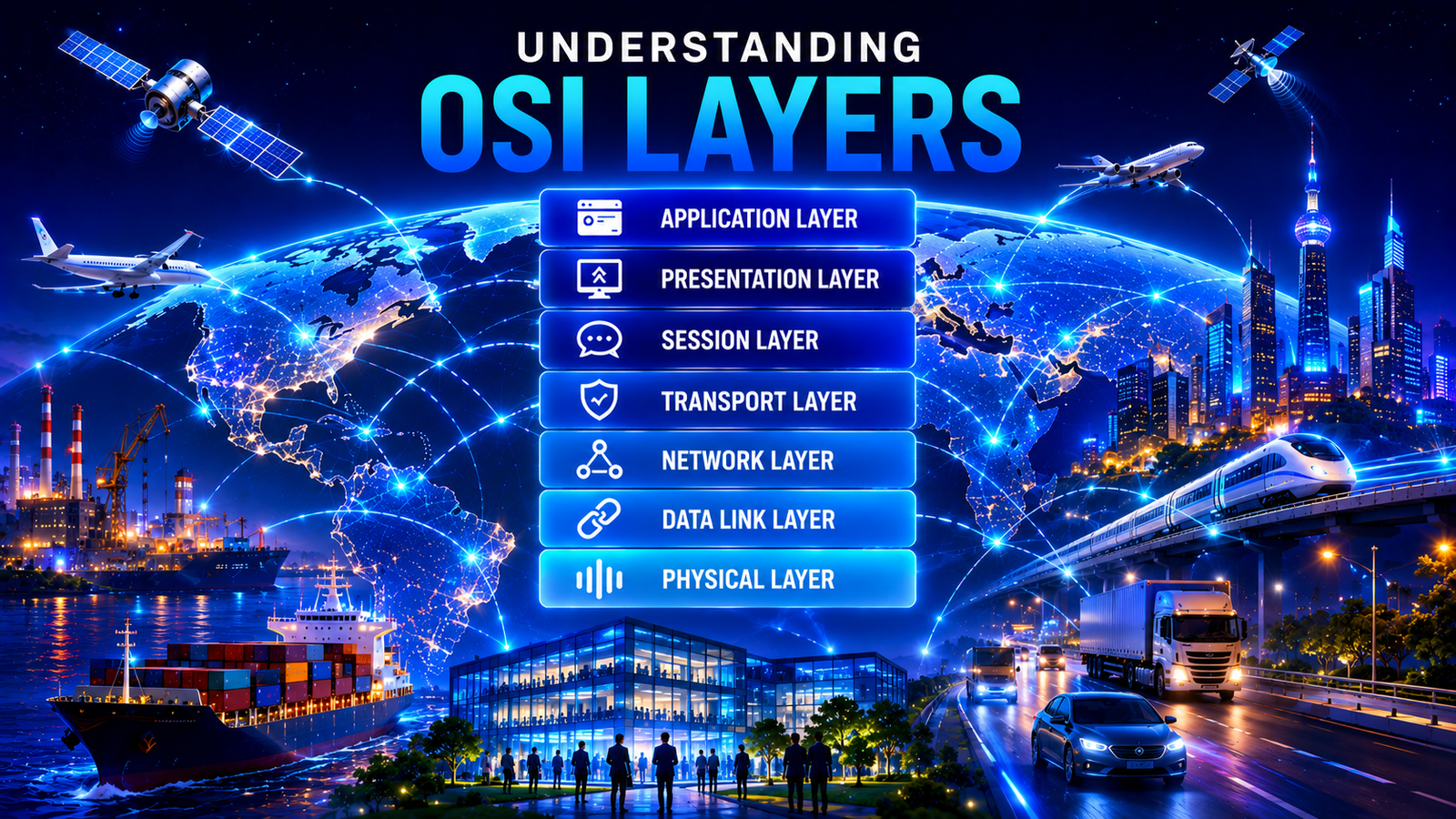
Understanding the OSI Layers
Introduction
Modern computer networks enable billions of devices to communicate and exchange information across homes, businesses, governments, educational institutions, and the Internet. Whether sending an email, browsing a website, streaming a video, making a video call, or accessing cloud services, every network communication follows a structured process to ensure that data reaches its intended destination accurately and efficiently.
As computer networks evolved, manufacturers developed their own proprietary networking technologies and communication methods. These incompatible implementations created challenges when connecting systems from different vendors. To address this problem, the International Organization for Standardization (ISO) introduced the Open Systems Interconnection (OSI) Model, a standardized conceptual framework that describes how network communication should occur between different systems.
Rather than defining specific networking protocols, the OSI Model divides network communication into seven distinct layers, with each layer responsible for a specific set of functions. This layered approach simplifies the design, implementation, management, and troubleshooting of computer networks while promoting interoperability between different hardware, software, and communication technologies.
Although today’s Internet operates primarily on the TCP/IP protocol suite rather than the OSI protocols, the OSI Model remains the universal reference model used to understand networking concepts, explain communication processes, classify protocols and devices, troubleshoot network problems, and design network architectures. Its clear separation of responsibilities has made it one of the most influential frameworks in networking and cybersecurity education.
What Is the OSI Model?
The Open Systems Interconnection (OSI) Model is a conceptual reference model developed by the International Organization for Standardization (ISO) to standardize the way computer systems communicate over a network. It provides a structured framework that divides network communication into seven logical layers, with each layer responsible for performing specific networking functions.
Instead of describing how a particular protocol operates, the OSI Model explains how communication should be organized between networked devices. Each layer performs a defined set of tasks, offers services to the layer above it, and relies on the services provided by the layer below it. Together, the seven layers form a complete communication process that enables data to travel from one device to another.
The OSI Model is technology-neutral and protocol-independent. It can be applied to virtually any type of communication network regardless of the protocols, operating systems, hardware platforms, or vendors involved. This flexibility has made it the standard reference framework for studying and understanding network communication.
The OSI Model organizes network communication into seven logical layers, with each layer responsible for a specific aspect of the communication process. Together, these layers enable data to move systematically from the sending application on one device to the receiving application on another.
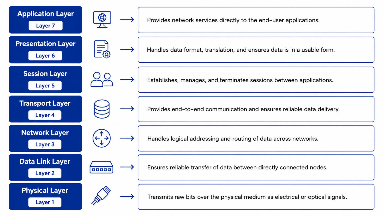
Each layer has clearly defined responsibilities and communicates only with its adjacent layers while logically interacting with the corresponding layer on the remote device. This layered architecture simplifies network design, enables interoperability between different systems, and provides a structured approach to understanding how data is transmitted across networks.
The OSI Model is used extensively to:
- Understand how network communication works.
- Design layered network architectures.
- Explain networking concepts.
- Classify networking protocols.
- Identify the roles of networking devices.
- Troubleshoot network connectivity issues.
- Provide a common language for networking professionals.
Although the OSI protocols themselves are not widely implemented, the model remains the foundation for networking education and serves as the universal reference framework for understanding modern computer networks.
Understanding the OSI Layers
The OSI Model organizes network communication into seven logical layers, each performing a specific function within the communication process. Together, these layers ensure that data can be prepared, transmitted, routed, delivered, and presented correctly between communicating devices.
Although each layer has distinct responsibilities, they do not operate independently. Every layer provides services to the layer above it while relying on the services provided by the layer below it. This layered approach simplifies network communication by separating complex tasks into manageable components.
Each of the seven layers serves a specific purpose and contributes to the successful transmission of data across a network. Understanding the role of each layer provides the foundation for learning how modern network communication works.
From Information to Data
Before network communication begins, a user creates information, such as writing an email, entering text into a web page, uploading a document, or streaming a video. This information is meaningful to humans but cannot be transmitted directly across a network.
When an application requests network communication, the information is converted into data that computers can process and exchange. From this point onward, the OSI Model operates on data, with each layer performing a specific function before passing it to the next layer.
As the data moves through the OSI Model, each layer performs its assigned responsibility and prepares the data for processing by the next layer. At the receiving device, the process occurs in reverse until the receiving application reconstructs and presents the original information to the user.
Layer 7 – Application Layer
The Application Layer is the topmost layer of the OSI Model and serves as the interface between end-user applications and the network. It provides network services that allow software applications to communicate with remote systems, enabling users to access resources and exchange information over a network.
Contrary to a common misconception, the Application Layer does not refer to the applications themselves, such as web browsers or email clients. Instead, it provides the networking services that these applications use to initiate and receive network communication.
At this point, the information created by the user has already been converted into application data. The Application Layer receives this data from the application and prepares it for processing by the lower layers of the OSI Model.
Its primary responsibilities include:
- Providing network services to user applications.
- Identifying communication partners.
- Determining the availability of network resources.
- Initiating and terminating application-level communication.
- Supporting user authentication where applicable.
Once the application data is ready for communication, it is passed to the Presentation Layer.
Layer 6 – Presentation Layer
The Presentation Layer is responsible for preparing data so that it can be understood by the receiving application. It ensures that data exchanged between different systems is represented in a common format, regardless of differences in operating systems, hardware architectures, or data encoding methods.
Often referred to as the syntax layer, it translates data into a standardized representation that both communicating systems can understand. It also performs functions such as data encryption, decryption, compression, and decompression to ensure that the data is secure, efficient to transmit, and correctly interpreted by the receiving system.
Its primary responsibilities include:
- Data translation and format conversion.
- Character encoding and decoding.
- Data encryption and decryption.
- Data compression and decompression.
- Ensuring consistent data representation between communicating systems.
After the data has been translated, formatted, encrypted, or compressed as required, it is passed to the Session Layer.
Layer 5 – Session Layer
The Session Layer establishes, manages, synchronizes, and terminates communication sessions between applications. A session represents an active communication channel that allows two applications to exchange data in an organized and coordinated manner.
This layer maintains the communication session throughout the exchange of data, coordinates synchronization between the communicating systems, and ensures that the session is terminated properly when communication is complete. If communication is interrupted, the Session Layer helps coordinate session recovery so that communication can continue without restarting the entire process.
Its primary responsibilities include:
- Establishing communication sessions.
- Managing active sessions.
- Synchronizing data exchanges.
- Recovering interrupted sessions.
- Gracefully terminating communication sessions.
Once the communication session has been established and managed, the data is passed to the Transport Layer.
Layer 4 – Transport Layer
The Transport Layer provides end-to-end communication between applications running on different devices. Its primary role is to ensure that data is delivered efficiently, reliably, and in the correct order between the communicating applications.
To improve transmission efficiency, the Transport Layer divides large blocks of data into smaller units that can be transmitted more effectively across the network. At the destination, these units are reassembled into the original data before being delivered to the upper layers. Depending on the communication requirements, this layer may provide reliable delivery with error recovery or prioritize speed for time-sensitive communications.
Its primary responsibilities include:
- End-to-end data delivery.
- Data segmentation and reassembly.
- Flow control.
- Error detection and recovery.
- Reliable or best-effort data transmission.
After preparing the data for end-to-end communication, it is passed to the Network Layer.
Layer 3 – Network Layer
The Network Layer is responsible for delivering data between different networks. It determines the most appropriate path that the data should follow from the source device to the destination device and performs logical addressing and routing.
When communication occurs across multiple interconnected networks, the Network Layer identifies the most suitable route and forwards the data toward its destination. This enables devices located anywhere in the world to communicate across local networks, metropolitan networks, wide area networks, and the Internet.
Its primary responsibilities include:
- Logical addressing.
- Packet routing.
- Path determination.
- Packet forwarding.
- Traffic management across multiple networks.
Once the transmission path has been determined, the data is passed to the Data Link Layer.
Layer 2 – Data Link Layer
The Data Link Layer is responsible for delivering data between devices connected to the same physical network. It prepares the data for transmission over the local network and helps ensure reliable communication between directly connected devices.
This layer detects transmission errors that may occur on the local network, controls access to the shared communication medium, and identifies devices using their physical hardware addresses. These functions help ensure that data reaches the correct device within the local network segment.
Its primary responsibilities include:
- Framing.
- Physical addressing (MAC addressing).
- Error detection.
- Media access control.
- Node-to-node communication.
Once the data has been prepared for transmission across the local network, it is passed to the Physical Layer.
Layer 1 – Physical Layer
The Physical Layer is the lowest layer of the OSI Model and is responsible for transmitting data across the physical communication medium. It defines the electrical, optical, mechanical, and signaling characteristics required to establish physical connectivity between communicating devices.
Unlike the higher layers, the Physical Layer does not interpret or modify the contents of the data. Instead, it converts the data into signals suitable for the transmission medium. Depending on the network technology, these signals may be transmitted as electrical signals over copper cables, light pulses through fiber-optic cables, or radio waves through wireless communication.
Its primary responsibilities include:
- Transmitting data over the physical communication medium.
- Defining signaling methods.
- Establishing physical connectivity.
- Specifying cables, connectors, and transmission media.
- Defining electrical and optical transmission characteristics.
At the receiving device, the incoming signals are received through the physical communication medium and passed to the higher layers of the OSI Model for further processing. Each layer performs its designated function until the original data reaches the receiving application, where it is presented to the user as meaningful information.
Why the OSI Model Was Developed
Before the OSI Model was introduced, computer networking lacked a common standard. Different vendors developed proprietary networking architectures, communication protocols, and hardware that worked only within their own product ecosystems. As a result, systems from different manufacturers often could not communicate with one another without custom gateways or specialized software.
This lack of interoperability created several challenges:
- Incompatible networking technologies
- Vendor-specific communication protocols
- Difficult integration between different systems
- Increased complexity in network design
- Limited scalability
- Higher implementation and maintenance costs
Recognizing the need for a universal communication framework, the International Organization for Standardization (ISO) initiated the OSI project in the late 1970s. The objective was not to replace existing networking technologies immediately but to establish a standardized architectural model that any vendor could follow when developing networking products and protocols.
The OSI Model introduced the concept of layered communication, where complex networking functions are divided into smaller, well-defined layers. Each layer performs a specific role independently while interacting with adjacent layers through standardized interfaces.
This layered design offered several important advantages:
- Standardized communication architecture
- Improved interoperability
- Simplified protocol development
- Easier troubleshooting
- Independent evolution of technologies
- Better modularity and flexibility
Although the networking industry eventually adopted the TCP/IP protocol suite as the practical foundation of the Internet, the architectural principles introduced by the OSI Model became universally accepted and continue to influence modern network design.
History and Evolution of the OSI Model
The rapid growth of computer networking during the 1970s highlighted the need for international communication standards. As organizations began connecting computers across different locations, the absence of a common networking architecture made interoperability increasingly difficult.
To address this challenge, the International Organization for Standardization (ISO) established a project to develop a universal networking framework that could be adopted globally. The result was the Open Systems Interconnection (OSI) Reference Model, formally published in 1984 as ISO 7498.
The OSI initiative represented one of the first comprehensive efforts to standardize network communication by separating networking functions into independent layers. This approach enabled vendors to develop compatible technologies without requiring every component of the communication process to be redesigned.
During the 1980s, several protocol suites were developed based on the OSI architecture. However, at the same time, the TCP/IP protocol suite, originally developed for the ARPANET project, gained widespread adoption due to its simplicity, reliability, and successful implementation across interconnected networks. As the Internet expanded globally, TCP/IP became the dominant protocol suite used for real-world communication.
Although the OSI protocol suite itself was gradually abandoned, the OSI Model remained highly valuable because of its logical architecture and clear separation of networking functions. Educational institutions, networking vendors, standards organizations, certification programs, and IT professionals continued using the OSI Model to explain network communication, classify protocols, identify device responsibilities, and troubleshoot networking problems.
Today, the OSI Model remains the most widely recognized conceptual framework for understanding computer networking. While modern networks rely on the TCP/IP protocol suite for actual communication, the OSI Model continues to serve as the universal reference model for learning, designing, documenting, and analyzing network architectures.
Objectives of the OSI Model
The OSI Model was developed to establish a standardized framework for network communication that could be understood and adopted universally. Rather than defining specific communication protocols, it provides a structured architecture that describes how different networking functions should work together to enable reliable data exchange between systems.
The primary objectives of the OSI Model include:
Standardize Network Communication
One of the primary objectives of the OSI Model is to establish a common framework for network communication. Before its introduction, networking technologies were largely proprietary, making interoperability between systems from different vendors difficult. The OSI Model provides a standardized architectural approach that enables networking technologies to be designed using consistent principles.
Promote Interoperability
The OSI Model encourages interoperability by defining clear functional boundaries between layers. Systems developed by different manufacturers can communicate more effectively when they follow common architectural concepts, reducing vendor dependency and improving compatibility.
Simplify Network Design
Dividing network communication into separate layers allows each networking function to be developed independently. This modular approach simplifies the design, implementation, and maintenance of network architectures while reducing overall complexity.
Support Protocol Independence
The OSI Model is independent of any particular protocol or technology. Existing protocols can evolve, and new protocols can be introduced without changing the overall layered architecture, ensuring long-term flexibility.
Improve Troubleshooting
The layered structure enables administrators and engineers to isolate problems systematically. Instead of investigating an entire communication process, issues can be analyzed layer by layer, making troubleshooting more efficient and methodical.
Encourage Modular Development
Each layer performs a specific function while relying on services provided by the layer below and offering services to the layer above. This modular design allows individual components to be improved or replaced without affecting the entire communication process.
Provide a Common Language
The OSI Model establishes a universal terminology that is widely used by networking professionals, educators, standards organizations, and vendors. Referring to communication problems, protocols, or devices by their associated OSI layer provides a consistent method for discussing network technologies.
Benefits of the OSI Model
Although the OSI protocol suite was never widely adopted, the OSI Model continues to offer significant benefits because of its logical architecture and standardized approach to network communication.
Improved Understanding of Network Communication
The layered architecture simplifies complex networking concepts by dividing communication into manageable functional components. This makes it easier for students and professionals to understand how data travels across networks.
Simplified Network Design
The OSI Model provides a structured framework that helps architects design scalable, modular, and maintainable network infrastructures by separating communication into well-defined layers.
Easier Troubleshooting
One of the most significant advantages of the OSI Model is its usefulness in troubleshooting. Engineers can identify whether a problem exists at the Physical, Data Link, Network, Transport, or Application layer, allowing faults to be isolated more quickly.
Vendor-Neutral Framework
The OSI Model is not tied to any hardware manufacturer, software vendor, or networking technology. Its vendor-neutral architecture makes it applicable across diverse networking environments.
Flexibility and Scalability
Since each layer operates independently, improvements or changes to one layer generally have minimal impact on the others. This flexibility supports the continuous evolution of networking technologies.
Foundation for Networking Education
The OSI Model remains the standard framework used in networking textbooks, academic programs, technical documentation, professional certifications, and industry training because it provides a logical method for explaining network communication.
Better Communication Among Professionals
Using standardized layer terminology allows engineers, architects, vendors, and support teams to communicate more effectively when discussing network design, protocol behavior, and troubleshooting activities.
Principles of Layered Network Architecture
The OSI Model is based on the principle of layered architecture, where complex communication processes are divided into multiple logical layers. Each layer performs a specific set of functions while cooperating with adjacent layers to deliver data from one system to another.
This approach provides structure, modularity, and flexibility while reducing the complexity of network communication.
The key principles of layered network architecture include:
Separation of Responsibilities
Each layer has a clearly defined purpose and performs only the functions assigned to it. This separation prevents unnecessary overlap between layers and simplifies both implementation and maintenance.
Layer Independence
Each layer operates independently of the internal implementation of other layers. As long as the services and interfaces remain consistent, technologies within a layer can evolve without requiring changes throughout the entire architecture.
Service-Oriented Design
Every layer provides services to the layer immediately above it while using services provided by the layer below. This service-oriented approach creates a structured communication hierarchy.
Standardized Interfaces
Communication between adjacent layers occurs through well-defined interfaces. Standardized interfaces allow different implementations to work together while maintaining consistent behavior.
Encapsulation
As data moves down the protocol stack, each layer adds its own control information required to perform its specific function. This process, known as encapsulation, enables reliable communication across the network.
Decapsulation
When data reaches the destination, each receiving layer removes and processes the information added by its corresponding sending layer. This reverse process reconstructs the original application data for the receiving application.
Peer-to-Peer Communication
Although data physically passes through every layer on both communicating devices, each layer logically communicates with its corresponding layer on the remote system using protocols designed for that layer.
Modularity
The layered architecture promotes modular development by allowing protocols, technologies, and hardware components to be developed, upgraded, or replaced independently, provided they continue to support the required services and interfaces.
These architectural principles have influenced modern networking for decades and continue to underpin the design of communication protocols, network technologies, and distributed systems, regardless of whether the underlying implementation follows the OSI Model or the TCP/IP protocol suite.
OSI Model vs TCP/IP Model
The OSI Model and the TCP/IP Model are the two most widely recognized networking models used to describe how data is transmitted across computer networks. Although they share many similarities, they were developed for different purposes and continue to play different roles in modern networking.
The OSI Model is a conceptual reference model developed by the International Organization for Standardization (ISO). It provides a standardized framework for understanding network communication by dividing the communication process into seven logical layers. Rather than defining a specific protocol suite, the OSI Model explains the functions that should be performed at each stage of network communication. This makes it an invaluable tool for learning, designing, analyzing, and troubleshooting computer networks.
The TCP/IP Model, also known as the Internet Protocol Suite, is a practical networking model developed to support communication across interconnected networks. Unlike the OSI Model, TCP/IP defines both a networking architecture and a collection of communication protocols that enable real-world data transmission. It forms the foundation of modern networking and is the protocol suite used throughout the Internet.
Although the TCP/IP Model was developed independently of the OSI Model, the two models perform many similar networking functions. The primary difference is that the OSI Model separates communication into seven distinct layers, whereas the TCP/IP Model combines several of these functions into four layers.
OSI Model and TCP/IP Model Layer Comparison
Although the OSI Model and the TCP/IP Model differ in the number of layers and their design philosophy, they perform many of the same networking functions. The primary difference is that the OSI Model separates network communication into seven distinct layers, whereas the TCP/IP Model combines several of these functions into four layers.
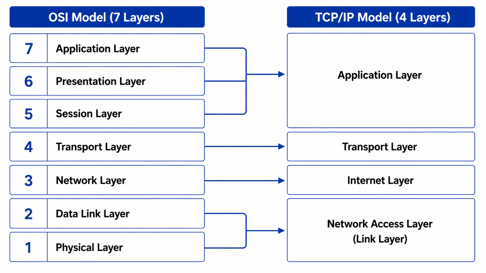
In the TCP/IP Model, the Application Layer combines the responsibilities of the Application, Presentation, and Session layers of the OSI Model. Similarly, the Network Access Layer (also known as the Link Layer) combines the functions performed by the Data Link and Physical layers. The Transport Layer and Network Layer of the OSI Model closely correspond to the Transport Layer and Internet Layer of the TCP/IP Model, respectively.
Although the two models organize networking functions differently, they describe the same overall communication process. The OSI Model provides a detailed conceptual framework for understanding network communication by separating it into seven logical layers, whereas the TCP/IP Model groups related networking functions into four layers to provide a practical protocol architecture for modern computer networks and the Internet.
Key Differences Between the OSI Model and TCP/IP Model
Although both models describe the same communication process, they differ significantly in their architecture, design objectives, and implementation. The OSI Model was developed as a vendor-neutral reference framework for standardizing network communication, whereas the TCP/IP Model was designed as a practical protocol architecture to support real-world data communication across interconnected networks.
The following table highlights the key differences between the two models:
| Feature | OSI Model | TCP/IP Model |
|---|---|---|
| Developed By | ISO | DARPA |
| Number of Layers | 7 | 4 |
| Purpose | Conceptual reference model | Practical implementation model |
| Protocol Support | Protocol-independent | Based on the TCP/IP protocol suite |
| Primary Use | Learning, design, architecture, and troubleshooting | Internet and network communication |
| Layer Design | Seven distinct functional layers | Four combined functional layers |
| Adoption | Used as the universal reference model | Universally implemented across networks |
The OSI Model focuses on explaining how network communication should be organized, making it an essential framework for education, architecture, and troubleshooting. In contrast, the TCP/IP Model defines the protocols used for actual communication and provides the foundation for virtually all modern computer networks and the Internet.
Why Did TCP/IP Become the De Facto Standard?
Although the OSI Model provides a more detailed and structured description of network communication, it was introduced after TCP/IP had already gained significant adoption. During the development of ARPANET and the early Internet, the TCP/IP protocol suite was successfully implemented and widely deployed across universities, research institutions, government organizations, and eventually commercial networks.
As Internet adoption accelerated throughout the 1980s and 1990s, TCP/IP became the common protocol suite used by operating systems, networking equipment manufacturers, Internet service providers, and software vendors. Its proven reliability, scalability, interoperability, and open standards encouraged widespread adoption across virtually every type of network.
By contrast, the OSI protocol suite experienced limited commercial deployment. While the OSI Model itself gained universal acceptance as a reference framework, its associated protocols never achieved the same level of adoption as TCP/IP.
Every Internet connected device, including computers, smartphones, servers, cloud platforms, IoT devices, and networking equipment, communicates using the TCP/IP protocol suite. The OSI Model, however, continues to serve as the universal reference framework for understanding, designing, implementing, and troubleshooting network communication.
Protocols, Standards, and Technologies by OSI Layer
Although the OSI Model is a conceptual reference model, numerous protocols, standards, technologies, and communication methods operate at its various layers. Each layer is associated with specific protocols, standards, and technologies that perform the functions assigned to that layer, enabling devices to communicate efficiently across computer networks.
The following table provides an overview of the common protocols, standards, technologies, and transmission media associated with each layer of the OSI Model:
| OSI Layer | Protocols | Standards | Technologies / Media | Primary Purpose |
|---|---|---|---|---|
| Layer 7 – Application | HTTP, HTTPS, FTP, SFTP, TFTP, SMTP, POP3, IMAP, DNS, DHCP, SNMP, SSH, Telnet, NTP | MIME | — | Provides network services that enable applications to communicate over a network. |
| Layer 6 – Presentation | TLS, SSL | ASCII, Unicode (UTF-8, UTF-16), EBCDIC, JPEG, PNG, GIF, TIFF, MPEG, MP3 | — | Translates, formats, encrypts, decrypts, compresses, and decompresses information for the Application Layer. |
| Layer 5 – Session | NetBIOS, RPC, SIP, PPTP | — | — | Establishes, manages, synchronizes, and terminates communication sessions between applications. |
| Layer 4 – Transport | TCP, UDP, SCTP, DCCP | — | — | Provides end-to-end communication, segmentation, flow control, error recovery, and reliable or best-effort data delivery. |
| Layer 3 – Network | IPv4, IPv6, ICMP, IGMP, IPsec, OSPF, RIP, EIGRP, BGP | — | — | Provides logical addressing, routing, and packet forwarding between interconnected networks. |
| Layer 2 – Data Link | PPP, HDLC, STP, LACP | IEEE 802.3 (Ethernet), IEEE 802.1Q (VLAN), IEEE 802.11 MAC | Ethernet, Wi-Fi | Provides framing, MAC addressing, media access control, and node-to-node communication. |
| Layer 1 – Physical | — | 10BASE-T, 100BASE-TX, 1000BASE-T, SONET/SDH | Twisted Pair, Coaxial Cable, Fiber Optic, Bluetooth | Defines the physical transmission of signals over wired and wireless communication media. |
This table serves as a general reference rather than an exhaustive list. Many protocols, standards, and technologies operate across multiple layers or interact with components at different layers of the networking stack. Nevertheless, the OSI Model provides a structured framework for understanding where these networking components primarily function and how they contribute to end-to-end communication.
Services and Interfaces
The layered architecture of the OSI Model is based on the concepts of services and interfaces. Rather than communicating directly with every other layer, each layer interacts only with the layers immediately above and below it. This structured approach simplifies communication and allows each layer to perform its assigned responsibilities independently.
A service is a function that one layer provides to the layer above it. For example, the Transport Layer provides end-to-end communication services to the Session Layer, while relying on the Network Layer to transfer data between networks. Similarly, every layer depends on the services provided by the layer below while offering its own services to the layer above.
An interface defines the boundary through which adjacent layers exchange information and services. It specifies how one layer requests services from another without exposing the internal implementation details of either layer. Because these interfaces remain well defined, technologies and protocols within a layer can evolve without affecting the operation of other layers.
This service-oriented architecture is one of the key strengths of the OSI Model. It promotes modularity, interoperability, scalability, easier maintenance, and simplified troubleshooting by allowing each layer to focus on a specific set of networking functions.
Layer-to-Layer Communication
Within a device, communication occurs vertically between adjacent layers of the OSI Model. Each layer receives information from the layer above, performs its designated function, and passes the processed information to the layer below. At the receiving device, the process occurs in the opposite direction as each layer processes the received information before passing it upward.
This interaction is known as layer-to-layer communication because each layer communicates only with its neighboring layers. A layer neither communicates directly with non-adjacent layers nor needs to understand how other layers perform their internal operations.
By limiting communication to adjacent layers, the OSI Model achieves a high degree of modularity. Changes made within one layer can often be implemented without affecting the operation of the remaining layers, provided the interfaces between adjacent layers remain unchanged.
Peer-to-Peer Communication Between Layers
While communication within a device occurs between adjacent layers, each layer also has a logical relationship with its corresponding layer on the remote device. This relationship is known as peer-to-peer communication.
For example, the Transport Layer on the sending device logically communicates with the Transport Layer on the receiving device. Likewise, the Network Layer communicates with the corresponding Network Layer, the Data Link Layer with the Data Link Layer, and the Physical Layer with the Physical Layer. Although the data physically travels through every layer and across the communication medium, each layer behaves as though it is communicating directly with its peer layer on the destination device.
This logical communication allows corresponding layers to interpret protocol information consistently, perform equivalent processing, and provide the services required for successful end-to-end communication.
The distinction between layer-to-layer communication, which occurs between adjacent layers within the same device, and peer-to-peer communication, which occurs logically between corresponding layers on different devices, is one of the fundamental concepts of the OSI Model. Understanding these communication mechanisms provides the foundation for learning data encapsulation, decapsulation, Protocol Data Units (PDUs), and the complete flow of data through the OSI Model.
Protocol Data Units (PDUs), Encapsulation, and Decapsulation
The OSI Model explains how communication occurs between networked devices by dividing the communication process into seven distinct layers, each responsible for a specific set of functions. While each layer performs its own tasks independently, successful communication depends on the coordinated interaction of all layers. To enable this layered communication, the OSI Model relies on three closely related concepts: Protocol Data Units (PDUs), encapsulation, and decapsulation.
Whenever an application sends information across a network, the data does not travel directly from the source application to the destination application. Instead, it passes sequentially through each OSI layer, where it is prepared for transmission. Every layer processes the information received from the layer above, adds the protocol information required to perform its specific functions, and forwards the resulting data to the next lower layer. This systematic preparation ensures that the data can be transported accurately, routed correctly, delivered reliably, and interpreted successfully by the receiving device.
The information processed at each layer is known as a Protocol Data Unit (PDU). As the data progresses through the protocol stack, its structure changes to reflect the responsibilities of each layer. Consequently, the PDU is identified by different names, including Data, Segment or Datagram, Packet, Frame, and Bits. Although these names differ, they all represent the same communication being processed at different stages of its journey through the OSI Model.
The process of adding protocol information to the data is called encapsulation. During encapsulation, each lower layer surrounds the complete PDU received from the layer above with its own protocol information. Most layers add a protocol header, while the Data Link layer adds both a header and a trailer. These protocol fields contain the information required by the corresponding layer on the receiving device to correctly process, verify, and forward the data.
When the transmitted information reaches the destination device, the reverse process, known as decapsulation, takes place. Each receiving layer examines the protocol information intended for that layer, performs the necessary processing, removes its own protocol information, and forwards the remaining PDU to the next higher layer. This process continues until the original application data is reconstructed and delivered to the destination application.
One of the most important concepts to understand is that the original application data remains unchanged throughout encapsulation. Rather than modifying the application data itself, each lower layer encapsulates the complete PDU received from the layer above by adding its own protocol information. As a result, the overall PDU grows as it moves toward the Physical layer, while the payload carried within it remains intact.
Understanding Protocol Data Units, encapsulation, and decapsulation provides the foundation for understanding how modern computer networks operate. These concepts explain how data is prepared for transmission, how each OSI layer contributes to the communication process, how corresponding layers exchange information, and how the original application data is successfully reconstructed at the destination. The following sections examine these concepts in detail and demonstrate how data moves through the OSI Model from the sending device to the receiving device.
PDU Names Across the OSI Layers
As data moves through the OSI Model, it is processed by each layer according to that layer’s specific responsibilities. Because every layer performs a different function, the format of the information changes throughout the communication process. This change in format is represented by a different Protocol Data Unit (PDU) at each stage of the protocol stack.
The Application, Presentation, and Session layers process the information as Data because these layers focus on providing application services, formatting information, and managing communication sessions. When the information reaches the Transport layer, it is encapsulated into a Segment when TCP is used or a Datagram when UDP is used. The Network layer then encapsulates the transport-layer PDU into a Packet, while the Data Link layer further encapsulates the packet into a Frame by adding a Layer 2 header and trailer. Finally, the Physical layer converts the frame into a stream of Bits for transmission across the communication medium.
Although the PDU name changes from one layer to another, the original application data remains unchanged throughout the communication process. Each lower layer receives the complete PDU from the layer above and encapsulates it with the protocol information required to perform its own functions. At the receiving device, the reverse process occurs as each layer removes only its own protocol information before passing the remaining PDU to the next higher layer until the original application data reaches the destination application.
The following table summarizes the Protocol Data Units used at each layer of the OSI Model, the protocol information added by each layer, and the primary purpose of each PDU.
| OSI Layer | PDU Name | Protocol Information Added | Description |
|---|---|---|---|
| Layer 7 – Application | Data | None | Creates and processes user data generated by network applications before it enters the communication process. |
| Layer 6 – Presentation | Data | None | Translates, encrypts, decrypts, compresses, or decompresses the application data into a format suitable for communication. |
| Layer 5 – Session | Data | None | Establishes, manages, synchronizes, and terminates communication sessions between applications. |
| Layer 4 – Transport | Segment (TCP) Datagram (UDP) | Transport Header (L4 Header) | Adds transport-layer information such as port numbers, sequencing, reliability, and flow control to support end-to-end communication. |
| Layer 3 – Network | Packet | Network Header (L3 Header) | Adds logical addressing and routing information required to forward data across interconnected networks. |
| Layer 2 – Data Link | Frame | Data Link Header (L2 Header) Data Link Trailer (L2 Trailer) | Adds physical addressing information and a trailer containing the Frame Check Sequence (FCS) for local delivery and error detection. |
| Layer 1 – Physical | Bits | None | Converts the frame into a stream of binary bits and transmits them as electrical, optical, or wireless signals across the communication medium. |
The names Data, Segment, Datagram, Packet, Frame, and Bits are standard networking terms used to identify the Protocol Data Unit at each layer of the OSI Model. Understanding these PDU names helps explain how data is progressively prepared for transmission, how protocol information is added during encapsulation, and how the original application data is reconstructed during decapsulation at the receiving device.
How Data Moves Through the OSI Model
Data communication through the OSI Model follows a structured, sequential process that begins at the source device, travels across the communication medium, and ends at the destination device. Rather than moving directly from one application to another, the information passes through each of the seven OSI layers on both devices. Every layer performs its designated functions before passing the processed information to the adjacent layer, ensuring that the data is correctly prepared for transmission and accurately reconstructed when it reaches its destination.
The communication process begins at the Application layer, where a user or application generates the information to be transmitted. As the data moves downward through the Presentation and Session layers, it may be translated into a common format, encrypted, compressed, or associated with an active communication session. Throughout these upper layers, the information remains identified as Data because it has not yet been prepared for network transmission.
When the information reaches the Transport layer, it is prepared for end-to-end communication. Depending on the transport protocol in use, the layer encapsulates the data into either a TCP Segment or a UDP Datagram by adding transport-layer protocol information such as source and destination port numbers, sequencing information, flow control, and reliability mechanisms where applicable. The Network layer then receives the complete Transport-layer PDU and adds logical addressing and routing information to create a Packet. The Data Link layer further encapsulates the packet into a Frame by adding a Layer 2 header and a Layer 2 trailer containing the information required for local delivery and error detection.
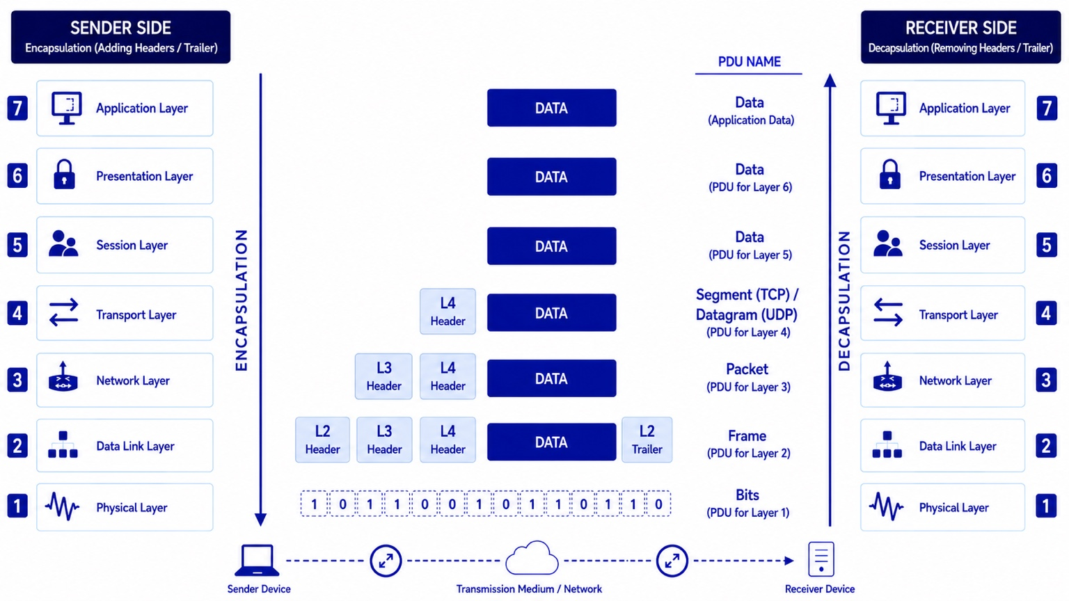
After the frame is created, it is passed to the Physical layer, where it is converted into a stream of Bits. These bits are transmitted across the communication medium as electrical signals, light pulses, or radio waves, depending on the underlying network technology. At this stage, the information is no longer viewed as structured protocol fields but as binary data represented by physical signals.
When the transmitted bits reach the destination device, the communication process is reversed. The Physical layer reconstructs the incoming bit stream into a frame and passes it to the Data Link layer. The Data Link layer verifies the integrity of the received frame, removes its header and trailer, and forwards the packet to the Network layer. The Network layer removes its header before passing the segment or datagram to the Transport layer. The Transport layer processes the transport-layer information, reassembles the original data if necessary, removes its header, and forwards the recovered data through the Session and Presentation layers until it finally reaches the destination application at the Application layer.
Throughout this entire communication process, the original application data remains unchanged. Each lower layer encapsulates the complete PDU received from the layer above by adding only the protocol information required to perform its own communication functions. At the destination, each layer removes only the protocol information that it previously added before forwarding the remaining PDU to the next higher layer. This systematic process enables reliable, standardized, and interoperable communication between networked devices.
Encapsulation
Encapsulation is the process of preparing data for transmission by progressively adding protocol information as the data moves downward through the layers of the OSI Model. Each layer receives the complete Protocol Data Unit (PDU) from the layer above, performs its assigned functions, adds the protocol information required for its own communication responsibilities, and passes the newly formed PDU to the next lower layer. This systematic process continues until the data reaches the Physical layer, where it is transmitted across the communication medium.
Encapsulation ensures that every layer contributes only the information necessary for its specific role in the communication process. The Transport layer adds information required for end-to-end communication between applications, the Network layer adds logical addressing and routing information for communication across interconnected networks, and the Data Link layer adds physical addressing and error detection information for communication over the local network. Each layer remains independent of the internal operations of the other layers while collectively enabling reliable communication.
One of the most important principles of encapsulation is that the original application data is never modified. Instead, each lower layer encapsulates the complete PDU received from the layer above by surrounding it with additional protocol information. As a result, the payload remains unchanged throughout the communication process, while the overall PDU becomes progressively larger as protocol headers and, in the case of the Data Link layer, a protocol trailer are added.
During encapsulation, the PDU changes its name as it moves through the protocol stack. The Application, Presentation, and Session layers process the information as Data. The Transport layer encapsulates the data into a Segment when TCP is used or a Datagram when UDP is used. The Network layer encapsulates the transport-layer PDU into a Packet, while the Data Link layer encapsulates the packet into a Frame. Finally, the Physical layer converts the completed frame into a stream of Bits for transmission.
Each protocol header contains information required by the corresponding layer on the receiving device. Depending on the protocol, this information may include source and destination addresses, port numbers, sequence numbers, protocol identifiers, control flags, or error-checking information. The Data Link layer is unique because it adds both a header and a trailer, with the trailer commonly containing the Frame Check Sequence (FCS) used to detect transmission errors.
Encapsulation is fundamental to layered network communication because it enables each OSI layer to perform its functions independently while preserving the integrity of the information received from the layer above. This modular approach simplifies protocol design, promotes interoperability between different networking technologies, and allows devices from different vendors to communicate using standardized protocols.
By the time the encapsulation process is complete, the original application data has been transformed into a stream of bits ready for transmission. Although the format of the information changes at each layer, the original payload remains intact and is protected by the protocol information added during encapsulation. This layered approach enables the receiving device to correctly interpret, verify, and reconstruct the original data during the decapsulation process.
Decapsulation
Decapsulation is the reverse of encapsulation. It is the process by which the receiving device removes the protocol information that was added during transmission, allowing the original application data to be reconstructed and delivered to the destination application. As the received information moves upward through the OSI Model, each layer processes the protocol information intended for that layer, removes its own header or trailer, and passes the remaining Protocol Data Unit (PDU) to the next higher layer.
The decapsulation process begins at the Physical layer, where the incoming electrical signals, optical pulses, or wireless radio waves are received and converted back into a stream of binary Bits. These bits are then reassembled into a Frame and passed to the Data Link layer for further processing.
At the Data Link layer, the frame is examined to verify its integrity using the information contained in the trailer, typically the Frame Check Sequence (FCS). If the frame passes the integrity check, the Data Link layer removes its header and trailer before forwarding the remaining Packet to the Network layer.
The Network layer examines the logical addressing information contained in the network header to confirm that the packet has reached its intended destination. After processing the routing and addressing information, the Network layer removes its own header and passes the remaining Segment or Datagram to the Transport layer.
The Transport layer processes the transport-layer protocol information, including source and destination port numbers, sequencing information, reliability mechanisms, and flow control where applicable. If multiple segments were transmitted, the Transport layer reassembles them into the correct order before removing its own header and passing the recovered Data to the Session layer.
The Session, Presentation, and Application layers complete the communication process. The Session layer manages the communication session, the Presentation layer performs any required decryption, decompression, or data translation, and the Application layer delivers the original information to the destination application exactly as it was generated by the sending device.
During decapsulation, each layer removes only the protocol information that it previously added during encapsulation. No layer removes or modifies the protocol information belonging to another layer. This separation of responsibilities ensures that every layer performs only its designated functions while maintaining the integrity of the communication process.
Decapsulation enables the receiving device to interpret the transmitted information correctly by processing the protocol information in the reverse order in which it was added. Together, encapsulation and decapsulation provide the structured mechanism that allows network devices to exchange information reliably, accurately, and consistently across diverse networking technologies and communication media.
Headers, Payload, and Trailers
Protocol Data Units (PDUs) consist of one or more protocol components that enable data to be transmitted, routed, delivered, and reconstructed successfully. As information moves through the OSI Model, the Transport, Network, and Data Link layers add protocol information that enables the receiving device to correctly interpret the communication. These protocol components are known as headers, payloads, and trailers.
A header is a block of protocol information added to the beginning of a Protocol Data Unit. Each layer adds its own header to perform the functions assigned to that layer. The header contains control information that enables the corresponding peer layer on the receiving device to identify, process, and deliver the data correctly. Depending on the protocol, a header may contain source and destination addresses, port numbers, sequence numbers, protocol identifiers, flags, routing information, or other control fields required for communication.
The payload is the information being carried by a Protocol Data Unit. At every stage of communication, the payload represents the complete PDU received from the layer above. For example, at the Transport layer, the payload consists of the application data. At the Network layer, the payload becomes the entire Transport-layer PDU, including its header. Similarly, at the Data Link layer, the payload is the complete Network-layer packet. This layered approach enables each protocol to treat the entire PDU received from the previous layer as the data it must transport.
One of the most important principles of encapsulation is that the payload itself remains unchanged. Each lower layer preserves the complete PDU received from the layer above and simply surrounds it with additional protocol information. As a result, the payload maintains its original content throughout the communication process, while the overall size of the Protocol Data Unit increases as new headers and, where applicable, trailers are added.
A trailer is a block of protocol information appended to the end of a Protocol Data Unit. Within the OSI Model, only the Data Link layer adds a trailer. The trailer typically contains a Frame Check Sequence (FCS) or similar error-detection value that enables the receiving Data Link layer to verify whether the frame was corrupted during transmission. If errors are detected, the receiving device can discard the corrupted frame and rely on higher-layer protocols, where applicable, to recover the lost information.
The combined use of headers, payloads, and trailers enables the layered communication process defined by the OSI Model. Headers provide the control information required by each protocol layer, the payload carries the information received from the previous layer, and the trailer provides additional integrity verification where required. Together, these protocol components ensure that data can be transmitted reliably across local networks, routed through interconnected networks, and reconstructed accurately when it reaches its destination.
Understanding the relationship between headers, payloads, and trailers is essential for understanding how network communication is organized across the OSI Model. These protocol components enable each layer to perform its designated functions independently while preserving the integrity of the information being transmitted. Together, they provide the addressing, control, sequencing, routing, and error-detection information required for data to travel reliably from the source device to the destination device and be reconstructed exactly as it was originally sent.
Role of PDUs, Encapsulation, and Decapsulation in Network Communication
Protocol Data Units (PDUs), encapsulation, and decapsulation form the foundation of modern network communication. They provide the structured mechanism that enables data to move efficiently through the OSI Model while allowing each layer to perform its designated responsibilities independently. Without these mechanisms, devices would have no standardized method for preparing, transmitting, receiving, and reconstructing information across diverse network technologies.
Protocol Data Units establish a common format for representing data at each layer of the communication process. By assigning a specific PDU to each layer, the OSI Model clearly defines how information is processed, encapsulated, transmitted, and decapsulated. This standardized approach enables networking professionals, protocol designers, and equipment manufacturers to communicate using a common terminology when designing, implementing, and troubleshooting networks.
Encapsulation plays a critical role by preparing data for transmission. As information moves downward through the protocol stack, each layer adds the protocol information required to perform its communication functions, such as application identification, end-to-end delivery, logical addressing, physical addressing, routing, sequencing, flow control, and error detection. Because each layer is responsible only for its own protocol information, the layered architecture remains modular, scalable, and independent.
At the destination device, decapsulation ensures that the transmitted information is processed in the correct order. Each layer examines the protocol information intended for it, removes only its own header or trailer, and passes the remaining Protocol Data Unit to the next higher layer. This systematic process guarantees that the original application data is reconstructed accurately before being delivered to the destination application.
These concepts also contribute significantly to interoperability. Devices manufactured by different vendors and operating across different network technologies can communicate successfully because they follow standardized protocols and encapsulation rules. Whether data travels across Ethernet, Wi-Fi, fiber-optic networks, cellular networks, or the Internet, the underlying principles of Protocol Data Units, encapsulation, and decapsulation remain consistent.
Understanding these concepts is equally important for network design, implementation, administration, and troubleshooting. Network engineers use them to analyze packet captures, identify protocol behavior, diagnose communication failures, verify protocol operation, and understand how data traverses local and wide area networks. Tools such as packet analyzers display the protocol headers added during encapsulation, allowing engineers to inspect communication at each layer and isolate problems more effectively.
Although the OSI Model is a conceptual framework, the principles of Protocol Data Units (PDUs), encapsulation, and decapsulation are implemented in real-world networking through protocol suites such as TCP/IP. These mechanisms provide the structured approach that enables data to be prepared for transmission, transported across interconnected networks, and accurately reconstructed at the destination. Together, they form one of the most fundamental concepts of the OSI Model and provide the foundation for reliable and interoperable network communication.
Conclusion
The Open Systems Interconnection (OSI) Model is one of the most fundamental concepts in computer networking. By dividing the complex process of network communication into seven distinct layers, it provides a structured framework for understanding how data is created, processed, transmitted, received, and delivered between networked devices. Each layer performs a specific set of functions, offers services to the layer above, and relies on the services provided by the layer below, creating a modular and standardized approach to communication.
The OSI Model encompasses the purpose and responsibilities of each of its seven layers, the principles of layered network architecture, layer-to-layer and peer-to-peer communication, Protocol Data Units (PDUs), encapsulation, decapsulation, and the role of headers, payloads, and trailers in preparing data for transmission. Together, these concepts illustrate how individual layers work independently while cooperating to provide reliable, efficient, and interoperable network communication.
Although modern computer networks primarily implement the TCP/IP protocol suite, the OSI Model remains the universal reference model for learning networking concepts, designing network architectures, analyzing protocol behavior, and troubleshooting communication problems. Its layered approach provides a common language that enables networking professionals, educators, protocol designers, equipment manufacturers, and technology vendors to describe and understand network communication in a consistent and standardized manner.
A thorough understanding of the OSI Model provides the foundation for understanding advanced networking concepts, communication protocols, network architectures, network security, and the technologies that enable reliable communication across interconnected systems. Whether designing networks, implementing communication protocols, analyzing packet captures, or troubleshooting connectivity issues, the principles of the OSI Model continue to provide a structured framework for understanding how modern networks operate.
Even decades after its introduction, the OSI Model remains an indispensable conceptual framework for networking. While it is not directly implemented as a protocol suite, its layered architecture continues to influence the design, development, and analysis of communication protocols and networking technologies. By providing a standardized way to describe and understand network communication, the OSI Model continues to serve as the universal reference framework for understanding, designing, implementing, and troubleshooting modern computer networks.